Difference between revisions of "Benderlink Ethernet Module for PINES to Vector"
From ATTWiki
(→Example Installation) |
|||
| Line 1: | Line 1: | ||
| − | |||
| − | |||
__NOTOC__ | __NOTOC__ | ||
| − | This is a single port Benderlink Ethernet Module that works with Benderlink for Pines to connect a TS-2000 (Pines) control to an Eaton Leonard Vector 1 measuring center. | + | {| border="0" cellpadding="5" cellspacing="0" align="none" width=700 |
| + | |- | ||
| + | | This is a single port Benderlink Ethernet Module that works with Benderlink for Pines to connect a TS-2000 (Pines) control to an Eaton Leonard Vector 1 measuring center. | ||
<br><br> | <br><br> | ||
This device is 100% Eaton Leonard Vector 1 Compatible. Any standard Vector 1 bender port can connect with this module. It is placed near the Vector 1 Laservision measuring center. | This device is 100% Eaton Leonard Vector 1 Compatible. Any standard Vector 1 bender port can connect with this module. It is placed near the Vector 1 Laservision measuring center. | ||
| + | | [[image:Blinklines2vector_pdfimage.jpg|300px]] | ||
| + | |} | ||
| + | |||
==About the Connections== | ==About the Connections== | ||
Revision as of 13:14, 2 May 2008
About the Connections
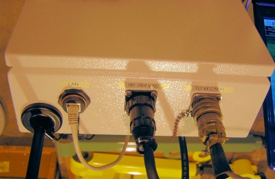
- One RJ-45 port - This connects to the Ethernet.
- One Military Connector - This connector follows the legacy Eaton Leonard style connection. You can connect standard communications cable with circular connectors at either end.
- One Power Port - Any voltage from 90 to 264 VAC accepted.
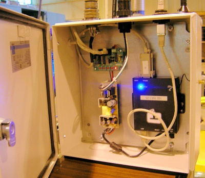
Inside the Module
Example Installation
This is an image of the box installed on a test bench computer running Benderlink for Eaton Leonard, which simulates Vector 1 Laservision communications.

Purchasing
This item can be purchased from our Online Store
Other Pages
- Benderlink Current Loop Module page
- Benderlink page
- Read more about the current loop board here: Communications Board for Eaton Leonard - CB-EL1


