Push Bending Profile Table
About Push Bending Profile Tables
|
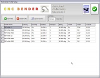
This is a sample Push Bend Profile Table. Each profile row contains a profile setup for a given radius. An unlimited number of profile values can be entered. Using this method of calculation, it is possible to calculate different Push Bends by indicating the new bend angles. |
Loading the Profile Table Menu
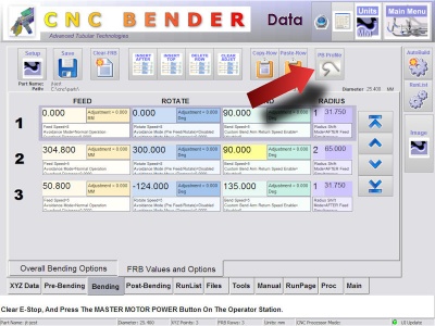
The Profile Table Setup is entered from the FRB screen only. The button is to the right in the button toolbar at the top.
The button is labeled "PB Profile" which stands for "Push Bending Profile."
Profile Values
| Value Name | Description | ||
|---|---|---|---|
| Profile Name | The "Profile Name" is what you use to identify a profile in the rest of CNC Bender. | ||
| Arm Angle | This is the final angle of the arm during Push Bending. | ||
| Arm vAdjust | This allows the velocity of the bend arm to be adjusted by a percentage of the original calculated velocity. | ||
| Feed Position | This is how far the carriage must travel to achieve the "@ Degrees" value programmed at the far right side of the table. For example, to achieve a bend angle of 90 degrees may require the carriage to move forward 10 inches. These two values combined allow CNC Bender to calculate other bend angle values (which translate to carriage motion) for this Profile. | ||
| Feed Speed | This is the speed (1-10) of the carriage during the bend for this profile. The speed of the carriage is also used to calculate a starting bend arm motion speed. The two are then directly proportional. For example, an increase in Feed speed will cause an increase in the calculated Bend Arm velocity so that the two stay synchronized when the bend arm is moving to its final push-bend location. If the calculated Bend Arm velocity is ever greater than the bender's maximum bend arm speed, then CNC Bender will cap the value at the maximum. If this happens, then a remark is placed in the Processlist just before the Push Bend. | ||
| @ Degrees | This is the angle of the tube that is achieved by the "Feed Position" value above. | ||
| Twist ON | This switches the rotational twist ON/OFF in the profile.
| ||
| Twist CCW | This controls the direction of the twist. The choices are CCW or CW from the front of the bender.
| ||
| Twist Gear | This controls the gear in degrees relative to the Feed axis. The value can be as low as 0.002 degrees per millimeter. If the value is set to 1, then the rotation axis rotates 1 degree for every 1 millimeter the Feed axis moves forward. If the value is less than 0.002, then the rotate does not move.
| ||
| |||
How it Works
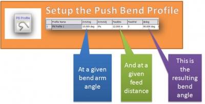
See this diagram as an illustration of the three foundation values used to calculate the bend angle in push bending.
Other Pages
- See CNC Bender v11-20081230 for information on the first version to enable HITCH FEED Push Bending with Twist Gearing
- See CNC Bender v11-20080424 for information on the first version to enable Push Bending
- See Push Bending
- See Helical Coil

