How to Switch the OD Mesh On/Off
Contents |
Entities Described
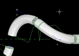
The OD Mesh can be composed of two types of entities - either WIRE or SURFACE. Either can be switched on or off independently in TubeCAD. This page describes ways to control them.
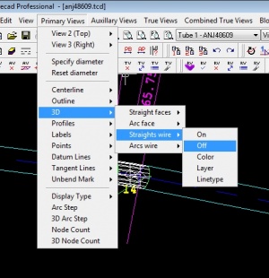
Switch Straights Wire
|
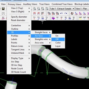
Switch the straights WIRE mesh off in the straights by using the Primary Views>3D>Straights wire>On/Off |
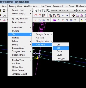
Switch Arcs Wire
|
Switch the arcs WIRE mesh off in the straights by using the Primary Views>3D>Arcs wire>On/Off |
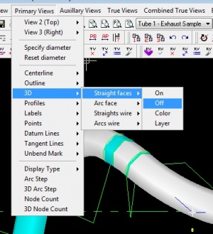
Switch Straights Faces
|
Switch the straights surface mesh off in the straights by using the Primary Views>3D>Straights faces>On/Off |
Switch Arcs Wire
|
Switch the arcs surface mesh off in the straights by using the Primary Views>3D>Arcs faces>On/Off |
Step 2: Load TubeCAD Pro and Initialize the Units
|
Step 3: Start the DXF File Import Feature
|
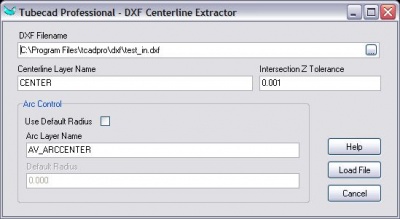
In the File pulldown menu, select the Import - DXF File command. Select the DXF file to import then press OK.
|
Step 4: Organize the Layout
|
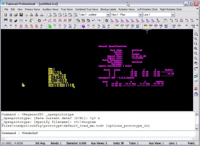
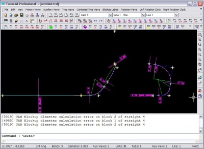
The display will change. It may look something like this. If you see nothing, then press the Zoom Extents feature.
|
Step 5: Set the Diameter
|
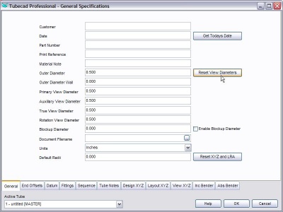
The incoming data will not contain a diameter, so you can set that value in the General Spec menu.
|
|
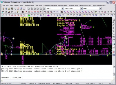
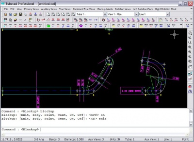
The image will display something like this: |
Step 6: Zoom Extents
|
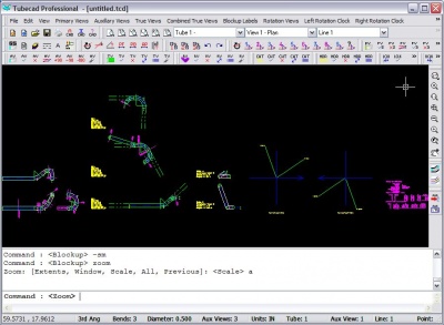
Zoom to the extents to see the entire layout.
|
Other Pages
Go back to TubeCAD Pro
