Difference between revisions of "VTube-LASER v1.91"

From ATTWiki
Jump to: navigation, search
(25px Other Changes)
(25px NEW: Expanded XYZ Deviation Grid Window)
Line 57: Line 57:
 
</table>
 
</table>
  
===[[image:Check.jpg|25px]] NEW: Expanded XYZ Deviation Grid Window===
+
===[[image:Check.jpg|25px]] NEW: Expanded XYZ Deviation Grid Window Can Send Data to MS Office===
 
<table cellpadding=10>
 
<table cellpadding=10>
 
<tr valign=top>
 
<tr valign=top>

Revision as of 23:20, 26 June 2014

Vtube-laser logo.jpg

Revision 1.91


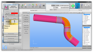
Vtube-laser 1.89 mainscreen.png


Check.jpg NEW: Use Leapfrog To Measure Tubes Longer Than the Arm's Reach

The new Leapfrog feature allows you to measure any length of tube by measuring three or more magnetic cones, leaping the cones with the FARO arm, then measuring the cones again - then continuing measuring from where you left off before the leap.

A leap can occur at any point during any tube measurement.

Leapfrog moves are more accurate than using the "Move Tube" command because they rely on more precise conical seats.

Vtube-lasesr-1.91-leapfrog-button.png

Vtube-lasesr-1.91-leapfrog points before leap.png

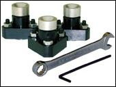
Vtube-laser-1.91-faro magnetic cones.png

Vtube-laser-1.91-leapfrog illustration.png

Vtube-lasesr-1.91-leapfrog points after leap.png

Check.jpg NEW: PLUS and MINUS Tolerances for XYZ Intersection Deviations

VTube-LASER now handles direction tolerances for the XYZ intersection point data.

This means that all tolerances and PLUS or MINUS - rather than just a single value.

The data below is from the new Expanded Grid (see the next section). There are two columns of tolerance for each axis.

Vtube-laser-1.91-xportion expanded grid.png

Check.jpg NEW: Expanded XYZ Deviation Grid Window Can Send Data to MS Office

New XYZ Intersection Deviation values are available for easy display in the Expanded Grid window.

  • The new window allows you to copy the grid to the clipboard.

  • The new window allows you to automatically send the grid to Word or Excel if they are available on your system.

  • The tolerance cells can be edited in the expanded grid window.

Vtube-laser-1.91-xyzint grid output office.png

Vtube-laser-1.91-expanded-xyz deviation grid.png

Vtube-laser-1.91-expanded xyz intersection deviation edit tolerance.png

Check.jpg NEW: XYZ Intersection +/- Tolerance Values in Report

The new XYZ Intersection deviation values are included in reports:

  1. plus tolerance values
  2. minus tolerance values
  3. out of tolerance values

Vtube-laser-1.91-report xyz intersection deviation output full.png

Vtube-laser-1.91-report xyz intersection deviation output.png

Check.jpg NEW: Measurement Complete Dialog REDESIGNED

This new measurement complete dialog gives you more choices than before. It no longer assumes that you want to use the current default alignment method.

You can choose from any one of the available alignment methods in this dialog.

Vtube-laser-1.91-measurementcomplete dialog.png

Check.jpg NEW: Direct Communications with Eaton Leonard Premier, EL2000, and Ve-log Benders

  • VTube now communicates with the older Eaton Leonard Premier, EL2000, and Ve-log controls.

El premier 001.jpg


Check.jpg Enhanced: Project Batch Report Output

  • We added a second type of report per a customer spec.
  • The reports are now built to both comma delimted and tab delimited files.
  • The reports can be sent directly to Excel.

Load the batch reporter in the Report menu of either STEP mode of LASER mode:

Vtube-1.90-project batch report button.png

Vtube-1.90-project batch report output.png

This is a sample report file:

Vtube-1.90-project batch report file1.png

If the batch reporter finds files with 0 or negative length straights, then it will issue a WARNING at the end of the report log and create a second report file containing a list of all the project files with these lengths:

Vtube-1.90-project batch report file2.png

Check.jpg Other Changes

  • IMPORTANT Fix to bug in END TRIM/EXTEND distances in the inspection reports. Sometimes the direction would be inverted. This has been resolved.

  • Now you can click on the scanner control labels to load the FARO Scanner control window.

  • VTube will automatically set the wall thickness to 0.001 inches or 0.025 millimeters when the value is set to zero during VTube-STEP solid model centerline calculations.

  • Now you can press Enter to close the information dialog.

  • The FARO calibration dialogs now show either Inches or Millimeters

  • Comments display in a dialog during project load

  • The Scanner Control settings are stored in VTube project files. In order for the scanner setup to be transferred into the arm, it is necessary to pull the arm from the cradle before the setup is transferred. VTube will ask you to move the arm when it is important.

  • The USB FARO driver icon is now displayed in the toolbar at the bottom of Windows.

  • The "Clear text" button in the editor box works again.

Vtube-laser-1.91 click label load scanner control.png

Other