Difference between revisions of "Scanning on a NEWPORT type table"
From ATTWiki
(→The Impact on Cylinder Calculations) |
(→Potential For Outliers At Normal Relfective Surfaces) |
||
| Line 65: | Line 65: | ||
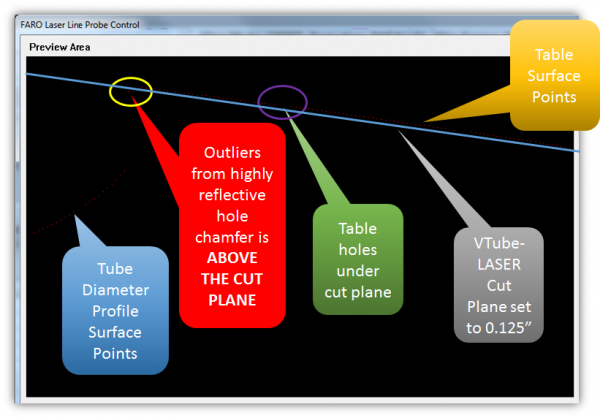
Notice that the chamfer that is normal to the laser and the camera is showing a bubble outlier. (Click on the image to see a closer view of this screen shot.) The effect is that the camera sees points where the is no object in space.<br><br> | Notice that the chamfer that is normal to the laser and the camera is showing a bubble outlier. (Click on the image to see a closer view of this screen shot.) The effect is that the camera sees points where the is no object in space.<br><br> | ||
One way to overcome this bubble is to increase the cut plane offset. In this case, the offset was set to 1 inch.<br><br> | One way to overcome this bubble is to increase the cut plane offset. In this case, the offset was set to 1 inch.<br><br> | ||
| − | Another way to overcome this issue is to place a darker surface (a mat or paint) in the table.</td> | + | Another way to overcome this issue is to place a darker surface (a mat or paint) in the table. |
| + | [[image:vtube-laser_closeup_outliers.png|200px]]</td> | ||
<td> | <td> | ||
[[image:Faro_LLP_Control_Newport_Table.png|600px]] | [[image:Faro_LLP_Control_Newport_Table.png|600px]] | ||
| Line 74: | Line 75: | ||
</table> | </table> | ||
<br> | <br> | ||
| − | |||
== The Impact on Cylinder Calculations== | == The Impact on Cylinder Calculations== | ||
Revision as of 19:13, 13 April 2016
|
NEWPORT Tables
| Scanning on NEWPORT tables is possible with the FARO scanner system, but care must be taken because of the high reflectivity of the surfaces in the drilled and tapped holes. | |
Scanning Example
|
The image on right shows an example of scanning a tube on a Newport table. | |
Potential For Outliers At Normal Relfective Surfaces
The Impact on Cylinder Calculations
| If VTube uses these outliers to calculate the diameter, then often the cylinder fit math will fail to find a centerline - and VTube will ask you to remeasure the straight where the problem is occuring. | |
Other Pages
- Back to the VTube-STEP page
- Back to the VTube-LASER page


