Measuring Coping
|
This article discusses how to measure a coping along with the tube shape in VTube-LASER. The method is to find a way to measure the coping as if it were an additional straight on the end of the tube.
In order to do this, the pipe straight that joins the main pipe at the coping can be treated like and extra end-straight on the pipe in VTube-LASER
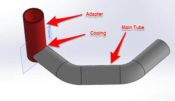
Idea: Design a Coping Adapter in a Solid Modelling Program
| In this example, we designed an adapter that simulates the joining pipe to the main pipe. | |
Import a Supravision Part in VTube-STEP
|
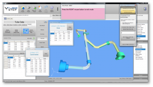
Import Supravision files into VTube-STEP using the Import/Export button in the navigation pane. |
|
About Supravision Files
|
Supravision files usually have a filename extension of $$$. |
|
Other Pages
- Back to the VTube-STEP page
- Back to the VTube-LASER page


