Difference between revisions of "CNC Bender v12-20100827"
| Line 38: | Line 38: | ||
<br><br> | <br><br> | ||
| − | ===[[image:Check.jpg|25px]] ENHANCED - Run Buttons | + | ===[[image:Check.jpg|25px]] ENHANCED - Run Buttons Advance a STEP In STEP Mode only when CLEAR === |
<table cellpadding=10> | <table cellpadding=10> | ||
<tr valign=top> | <tr valign=top> | ||
Revision as of 19:46, 26 August 2010
 ENHANCED - Run Buttons Check for CLEAR to Run Cycle
|
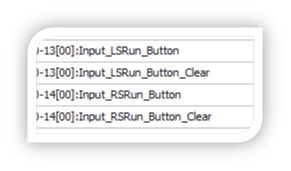
The processlist builder now uses a "Wait For Run Buttons Clear" command to test for clear run buttons before continuing the cycle. This protects against the run buttons being permanently enabled and causing the machine to run without the buttons being pressed. |
[BIGDISPLAY] Waiting for RUN BUTTONS CLEAR [DISPLAY] Next Step: (Pre-Bend) Wait for the run buttons to CLEAR Wait For Run Buttons Clear |
 ENHANCED - Run Buttons Advance a STEP In STEP Mode only when CLEAR
|
Now the release of the run buttons is what triggers CNC Bender to advanced to the next step in step mode. |
|
 NEW - Servo Status Grid Now Always Visible on Main Screen
|
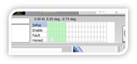
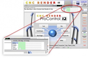
The status of up to 20 servo axes are now displayed at all times in a grid on the top of the screen. |
|
 NEW - BIG Messages
|
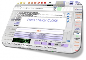
For important events, CNC Bender now displays large messages for short periods of time. This gives operators large, clear, and friendly messages of what step needs to be taken next.
|
|
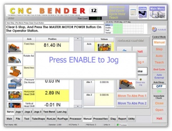
 NEW - Can Require ENABLE Button Press to Jog
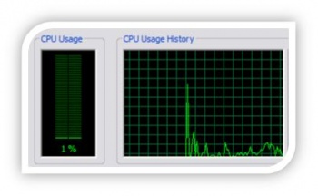
 ENHANCED - CNC Processor CPU Usage DECREASED to 25%
|
CNC Bender was optimized so that CNC Bender / CNC Processor CPU Usage was dropped from 75%-80% down to 25% or lower without any degradation in bender performance. The typical CPU usage under load rarely spikes beyond 35%.
Note: This optimization causes the CNC Bender user interface to run much more quickly. |
|||||
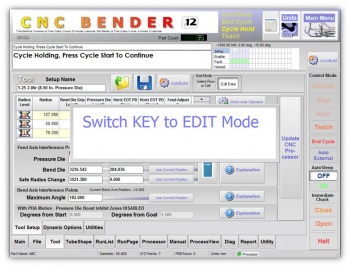
 NEW - KEY Switch to EDIT Feature
 NEW - MANDREL LUBE with TIMER in FOUR OPTION LISTS
|
The new Mandrel Lube With Timer option allows operators to lube the mandrel for a period of milliseconds
|
|
|
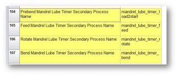
Setup the feature in the low level menu - general dynamic options by naming the secondary process list names:
|
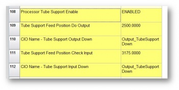
 NEW - EMBEDDED TUBE SUPPORT in CNC PROCESSOR
|
This feature allows CNC Bender's PROCESSOR to control when the tube support is lifted or dropped - and if the drop should be confirmed with an input.
|
|
 CHANGES - CNC Processor Configuration File
|
The following additions have been made to the configuration file:
|
ADD these to the CNCProcessor.cfg file: [Smart Inspect Logging] Enabled=0 Logging Method=TCPIP Filename=c:\cnc\logs\cncprocessor.sil TCPIP Address=192.168.0.190 [Loop] Main Loop Interval=0.100 Background Read Servo Loop Interval=0.100 |
|
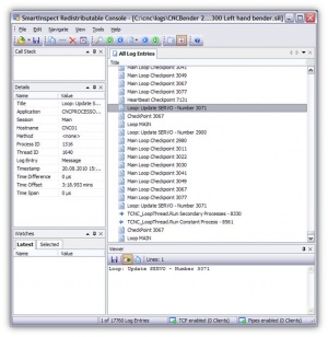
The image on the right is a screen shot of Smart Inspect logging from a CNC Processor session.
|
|
|
The items on the right can be removed from the configuration file. They are no longer used in CNC Processor. |
REMOVE these from the CNCProcessor.cfg file: [Loop] Power Off Manual Mode Pause=250 Power On Manual Mode Pause=250 Cycle Hold Pause=100 [PRIORITY] Master Loop Priority=10000 |
 NEW - Quiet EOT for Each Axis
|
During JOGGING - CNC Processor can check for EOT (end of travel) of an axis before it arrives at the true FAULT EOT. This gives the axis a chance to stop jogging before it arrives at a FAULT position or emergency switch.
|
The following additions have been made to the AXIS configuration file:
Example of what to add in each AXIS in the main.axislist file. The value shown here are typical of the FEED axis: Enable EOT=1 Low EOT=0 High EOT=3160 |
|
When the axis arrives at the programmed EOT, a Big Message (see above) displays on the screen that announces that the axis has arrived at the axis EOT - and CNC Processor stops the axis motion. |
Other Pages
- Back to CNC Bender
- Back to CNC Bender Software Updates
- See CNC Bender General Information
- See Teach Mode
- See Custom Commands

