Difference between revisions of "CNC Bender v11-20081230"
| Line 58: | Line 58: | ||
</td> | </td> | ||
</tr> | </tr> | ||
| + | </table> | ||
| + | |||
| + | <table> | ||
<tr> | <tr> | ||
| − | <td> | + | <td width="400"> |
| Line 70: | Line 73: | ||
<br><br> | <br><br> | ||
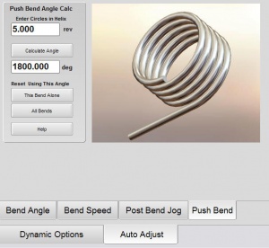
3 - The resulting angle is the angle necessary to create a helix with the programmed number of circles. | 3 - The resulting angle is the angle necessary to create a helix with the programmed number of circles. | ||
| − | |||
| − | |||
| − | |||
<br><br> | <br><br> | ||
4 - If necessary, further adjust the angle manually by touching the edit box for the bend angle. | 4 - If necessary, further adjust the angle manually by touching the edit box for the bend angle. | ||
| Line 79: | Line 79: | ||
<br><br> | <br><br> | ||
6 - Or press the "All Bends" if you intend to create multiple coils in one part. | 6 - Or press the "All Bends" if you intend to create multiple coils in one part. | ||
| − | |||
| − | |||
| − | |||
</td> | </td> | ||
Revision as of 02:56, 2 January 2009
 NEW - HITCH FEED Push Bending
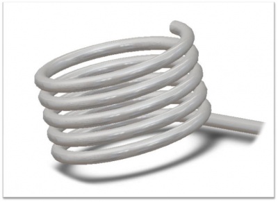
CNC Bender can now hitch feed during push bend to create a helical tube shape with many loops from a material that is much longer than the bender.
 NEW - Push Bend Twist GEARING
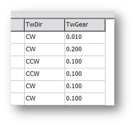
CNC Bender now uses electronic gearing in the rotational twist motion to the feed motion in order to create more accurate helical shapes. As the Feed axis moves forward, the Rotation axis rotates at a pre-programmed gear ratio in the Push Bending Profile page.
|
The older Twist Velocity column is replaced with the Twist Gear column. The lowest effective gear ratio value is 0.002 degrees per Feed axis millimeter.
|
The ratio is used as "degrees of twist" in the following formula:
Rotation Degrees of Twist PER Feed Axis 1 Millimeter
So a twist gear of 1 would cause the rotate to twist 1 degree per the feed axis 1 millimeter of motion during Push Bending.
 NEW - Calculate TOTAL BEND ANGLE for a Push Bend Coil
|
CNC Bender uses an AUTO ADJUST menu in option menus to automatically adjust and set values in the FRB (Feed Rotate Bend) page.
|
|
1 - Enter a value in the "Enter Circles in Helix" edit field. The value can be a floating point value.
|
 NEW - Automatic Bend Combine During XYZ to FRB Conversion
CNC Bender now allows you to automatically combine adjacent bends into a single bend if the adjacent bends meet a preprogrammed criteria controlled by the Low Level dynamic options.
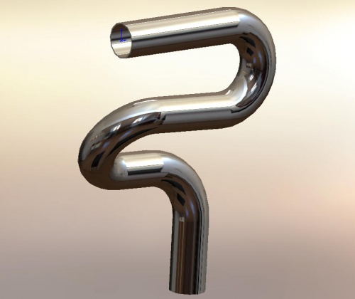
This feature is important because centerline XYZ data always represents bends that approach and exceed 180 degrees as two separate adjacent bends.
|
This part was drawn in SolidWorks and extracted by Benderlink for SolidWorks into XYZ data. |
|
|
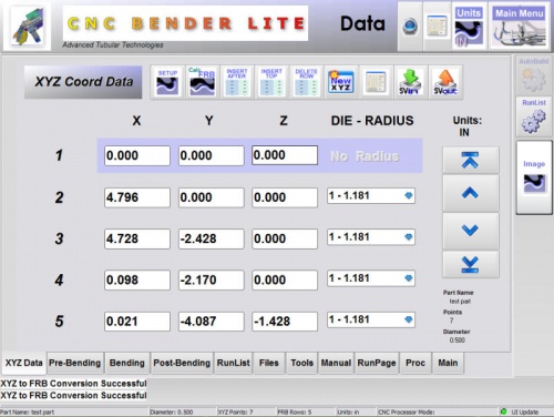
The data was imported into the XYZ data page of CNC Bender. |
|
|
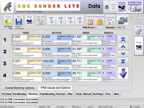
When XYZ to FRB conversion is made without the Combine Bends feature enabled, the result is five bends as shown in this FRB page.
|
|
|
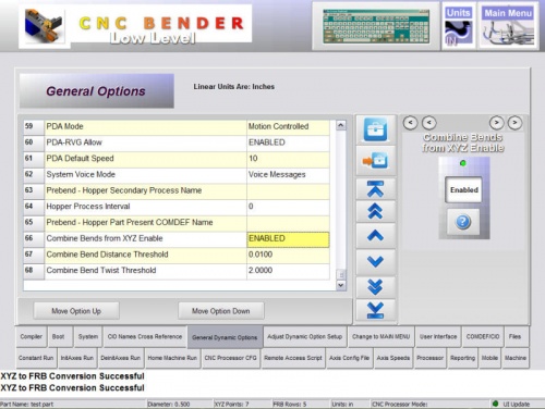
Enter the Low Level menu. The Combine Bends feature is enabled in the dynamic options.
|
|
|
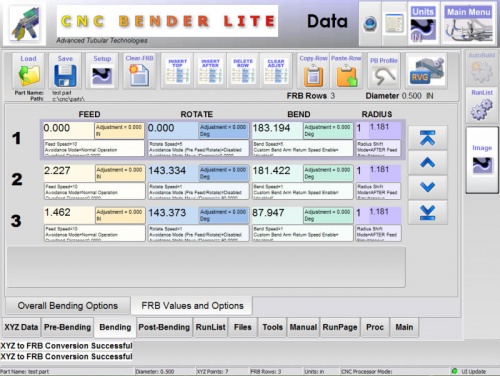
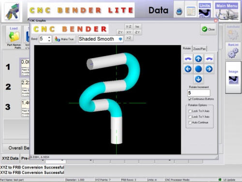
When XYZ to FRB conversion is made again, there are now only 3 bends in the FRB data. The first two bends are combined into high-angle bends that are proper for CNC benders. |
|
|
This is the resulting image in CNC Bender Bender Data menu: |
Other Pages
- Back to CNC Bender
- Back to CNC Bender Software Updates
- Read about Push Bending
- Read about Push Bend Profile Tables


