Difference between revisions of "Communications Board for Eaton Leonard - CB-EL1"
(→About) |
|||
| (43 intermediate revisions by one user not shown) | |||
| Line 1: | Line 1: | ||
| + | [[image:CB-EL1_logo.jpg]]<br> | ||
__TOC__ | __TOC__ | ||
[[image:cb-el1_array.jpg|right|450px]] | [[image:cb-el1_array.jpg|right|450px]] | ||
| + | |||
| + | |||
==About== | ==About== | ||
| − | This is the Advanced Tubular Technologies communications board designed to communicate with all [[VELOG]], [[EL-2000]], and [[Premier]] controls. | + | This is the Advanced Tubular Technologies communications board designed to communicate with all [[VELOG]], [[EL-2000]], and [[Premier]] controls.<br><br> |
| − | == | + | *This board allows us to communicate with any of the three Eaton Leonard bender models using our [[VTube-LASER]] software for bender corrections, or our [[Benderlink for Eaton Leonard]] software for offline programming and storage of Eaton Leonard data. <br><br> |
| − | + | ||
| − | + | *We also use this board in our [[Benderlink Ethernet Module]] that allows wired or wireless communications using Ethernet protocols.<br><br> | |
| + | |||
| + | *We offer this board as a direct replacement to the boards in the Premier controls. (EL-2000 and Velogs have this electronics built-in to the computer boards.)<br><br> | ||
| + | |||
| + | ==Vector 1 Laservision Side or Bender Side== | ||
| + | *As of version 2 of this board, the board can be set using jumpers to operate on either side of the connection - either as a BENDER or as a MEASURING CENTER. This means that the board can be used to connect non-Eaton Leonard benders to Laservision using the standard legacy Eaton Leonard protocol.<br><br> | ||
| + | |||
| + | *See this page for an example of how it can be used on the BENDER side of the connection: [[Benderlink Module - Laservision to Crown]] | ||
| + | <br><br> | ||
| + | |||
| + | ==Current Loop== | ||
| + | <ul> | ||
| + | The electronic protocol is referred to by Eaton Leonard as "current loop". | ||
| + | <br><br> | ||
| + | The protocol has been used for several decades and is still one of the standard ports provided on the Eaton Leonard measuring centers. | ||
| + | </ul> | ||
| + | <br><br> | ||
==Features== | ==Features== | ||
| − | There are several features and improvements in this board: | + | [[image:cb-el1_render1.jpg|right|250px]] |
| + | There are several features and improvements in our design of this board:<br><br> | ||
# The board requires only a single +5 volt power (The original design requires both +15 volt, -15 volt, and +5 volt power.) | # The board requires only a single +5 volt power (The original design requires both +15 volt, -15 volt, and +5 volt power.) | ||
| Line 20: | Line 40: | ||
# The communications connectors are easy-to-use RJ45 receptacles | # The communications connectors are easy-to-use RJ45 receptacles | ||
# The board is certified RoHS compliant (no lead solder) | # The board is certified RoHS compliant (no lead solder) | ||
| + | |||
| + | <br><br> | ||
| + | |||
| + | |||
| + | ==Communications Modes - LED Activity== | ||
| + | <table> | ||
| + | |||
| + | <tr> | ||
| + | <td width=200> | ||
| + | The CB-EL1 includes LEDs (Light Emitting Diodes) are that critical for diagnosing issues with Benderlink systems.<br><br> | ||
| + | This is how the board appears there is no activity and Benderlink is not monitoring for commands from the [[Vector]]. | ||
| + | </td> | ||
| + | <td> | ||
| + | [[image:cb-el1_running_not_monitoring.jpg|300px]] | ||
| + | </td> | ||
| + | </tr> | ||
| + | |||
| + | <tr> | ||
| + | <td width=200> | ||
| + | This is how the board appears when a Benderlink package is strobing the RTS and is ready for communications. The RTS LED will flash a couple of times a second. | ||
| + | </td> | ||
| + | <td> | ||
| + | [[image:cb-el1_running.jpg|300px]] | ||
| + | </td> | ||
| + | </tr> | ||
| + | |||
| + | <tr> | ||
| + | <td width=200> | ||
| + | This is how the LEDs appear when data is being sent from the Vector to Benderlink. The RX LED is more active than the TX LED. | ||
| + | </td> | ||
| + | <td> | ||
| + | [[image:cb-el1_receiving_data.jpg|300px]] | ||
| + | </td> | ||
| + | </tr> | ||
| + | |||
| + | <tr> | ||
| + | <td width=200> | ||
| + | This is how the LEDs appear when data is being sent from the Benderlink software to the Vector. The TX LED is more active than the RX LED. | ||
| + | </td> | ||
| + | <td> | ||
| + | [[image:cb-el1_sending_data.jpg|300px]] | ||
| + | </td> | ||
| + | </tr> | ||
| + | |||
| + | |||
| + | </table> | ||
| + | |||
| + | ==DataSheets== | ||
| + | |||
| + | |||
| + | <table cellpadding="15" width = 650> | ||
| + | <tr valign="top"> | ||
| + | <td bgcolor="#abbad1" width = 200> | ||
| + | [[image:advancedtubular_eatonleonard_currentloop.jpg|200px]] | ||
| + | </td> | ||
| + | <td bgcolor="#e3e4f5"> | ||
| + | [http://www.advancedtubular.com/cb-el1/advancedtubular_eatonleonard_currentloop.pdf Download a Datasheet] for the CB-EL1 board<br><br> | ||
| + | The datasheet contains the information found in this web page. | ||
| + | </td> | ||
| + | </tr> | ||
| + | </table> | ||
| + | |||
| + | <br><br> | ||
| + | |||
| + | ==Purchase== | ||
| + | You can purchase these from our store in kit form. See [http://www.advancedtubularstore.com/servlet/the-Electronic-Kit/Categories Electronic Kits Online] | ||
Latest revision as of 14:54, 9 July 2011
Contents |
About
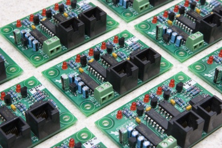
This is the Advanced Tubular Technologies communications board designed to communicate with all VELOG, EL-2000, and Premier controls.
- This board allows us to communicate with any of the three Eaton Leonard bender models using our VTube-LASER software for bender corrections, or our Benderlink for Eaton Leonard software for offline programming and storage of Eaton Leonard data.
- We also use this board in our Benderlink Ethernet Module that allows wired or wireless communications using Ethernet protocols.
- We offer this board as a direct replacement to the boards in the Premier controls. (EL-2000 and Velogs have this electronics built-in to the computer boards.)
Vector 1 Laservision Side or Bender Side
- As of version 2 of this board, the board can be set using jumpers to operate on either side of the connection - either as a BENDER or as a MEASURING CENTER. This means that the board can be used to connect non-Eaton Leonard benders to Laservision using the standard legacy Eaton Leonard protocol.
- See this page for an example of how it can be used on the BENDER side of the connection: Benderlink Module - Laservision to Crown
Current Loop
-
The electronic protocol is referred to by Eaton Leonard as "current loop".
The protocol has been used for several decades and is still one of the standard ports provided on the Eaton Leonard measuring centers.
Features
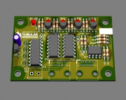
There are several features and improvements in our design of this board:
- The board requires only a single +5 volt power (The original design requires both +15 volt, -15 volt, and +5 volt power.)
- The simplified electronic design allowed for size reduction to 1/3 original size or the standard EL boards.
- This board includes LED indicators: Indicates power, transmission, and reception
- This board includes built-in current reversal protection. Reversing the power polarity will not destroy the board.
- This board uses screw terminals for power connection
- The communications connectors are easy-to-use RJ45 receptacles
- The board is certified RoHS compliant (no lead solder)
Communications Modes - LED Activity
|
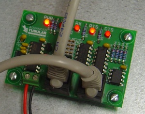
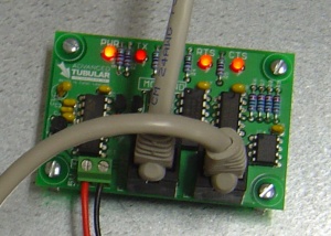
The CB-EL1 includes LEDs (Light Emitting Diodes) are that critical for diagnosing issues with Benderlink systems. |
|
|
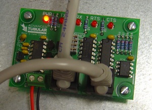
This is how the board appears when a Benderlink package is strobing the RTS and is ready for communications. The RTS LED will flash a couple of times a second. |
|
|
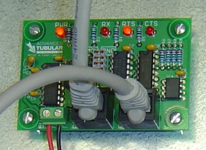
This is how the LEDs appear when data is being sent from the Vector to Benderlink. The RX LED is more active than the TX LED. |
|
|
This is how the LEDs appear when data is being sent from the Benderlink software to the Vector. The TX LED is more active than the RX LED. |
DataSheets
|
Download a Datasheet for the CB-EL1 board |
Purchase
You can purchase these from our store in kit form. See Electronic Kits Online
