VTube-LASER v2.5
Revision 2.5
|
 MAJOR NEW FEATURE: BEND PROFILE MEASURE
| VTube-LASER can now measure bend profile regions in order to calculate the measured radius and Out-of-round percentage in the bend. |
<tr valign=top>
<td width=300>
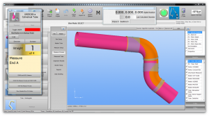
Bend Profile Measure Control
The Bend Profile measure control can be used in the middle of the Uniscan measure.
During a Uniscan tube measurement, you choose if you want to measure a bend's profile region.
To save time, VTube-LASER allows you to skip measuring the profile of non-critical bends.</td>
<td width=300>

</td>
</tr>
<tr valign=top> <td width=300>
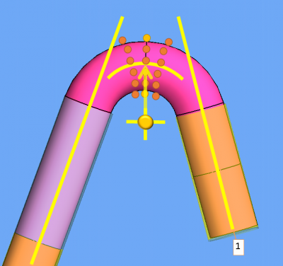
About the Bend Profile "Slice" Metaphor
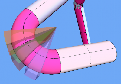
The metaphor "slice" is used to visualize the regions like slices of cake in the bend sections.
VTube uses these slice regions to group all surface points inside each of these regions. It then reports the one high and the one low value of the torus surface points in that slice region, and then uses those two values to calculate the out-of-round% values per slice region.
</td>
<td width=300>
</td>
</tr>
<tr valign=top> <td width=300>
Bend Profile Out-of-round Grid
SLICE COLUMN
In the Out-of-round grid (in Inspection Results), each slice is labeled as "Bend Number - Slice Number".
ANGLE COLUMN
Then next is shown the slice region angles in degrees. The default slice region width is 10 degrees. This value is controlled in the Other tab of Measure Setup.
LOW and HIGH COLUMNS
The Low and the High values are surface point distances from the centerline arc minus the radius of the nominal OD in each slice. (Each slice can have a unique nominal OD.)
OOR COLUMN
The Oor value is the difference between the high to low. This is the technical meaning of "Out-of-round".
OOR% COLUMN
The Oor% value is calculated from the high and the low differences. (The Oor% formula does not use the nominal diameter - so you can change the nominal OD to any value with effect on the Oor%.)
</td>
<td width=300>

</td>
</tr>
<tr valign=top> <td width=300>
Example High OOR% = 10.5
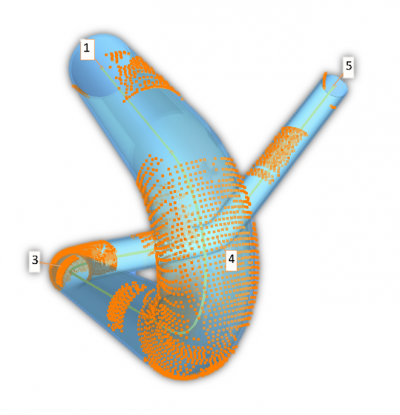
In the image on the right, you can see slices 5 through 10 in our mandrel bent Horn Demo tube.
Slices 7 and 8 have the greatest Out-of-round percentage at over 10.
Look closely at the center of the top of the bend, and you will see a ridge on the top of the tube is at a high point. This is where material flowed toward the top and the bottom of the bend during bending.
You may also detect the slightly reduced width from outside to the inside of the bend. All of this material flow is the reason for the OOR% at its highest in this region of the bend.
In slice 10 (OOR% of 8.4), the ridge on the top of the bend has faded, and the bend width from outside to inside is less flattened. The bend is recovering from the being out-of-round in this slice region.
</td>
<td width=300>
 </td>
</tr>
<tr valign=top>
<td width=300>
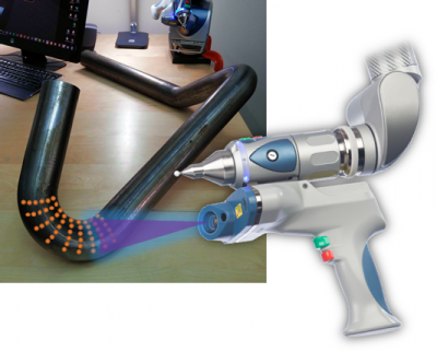
VTube-LASER Demo Tube 3 OOR% = 17 to 20
This is a closeup image of the bend in demo tube 3 that the FARO account managers carry with them.
This tube was not bent with a mandrel - which allows the material in the bend region to flow more than mandrel bent tubes.
</td>
<td width=300>
 </td>
</tr>
<td width=300>
VTube-LASER OOR Report
VTube-LASER can also build color-coded reports for printing the OOR data.
</td>
<td width=300>
 </td>
</tr>
</table>
 NEW: Bend Profile Radius Calculation
|
The Bend Profile measure feature also automatically calculates the centerline arc from the cloud data scanned around the bend. |
 NEW: BEFORE and AFTER TRIM Lengths Grid - Before The Actual Trim
|
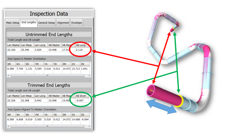
VTube now shows both the UNTRIMMED and the projected TRIM lengths to simulate the end length results if the end deviations were removed - but BEFORE the actual trim occurs.
|
 NEW: Communications with AIM Wire Benders
|
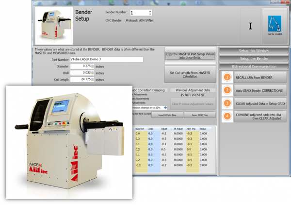
VTube-LASER and AIM wire benders can now communicate using the Supravision Network protocol. |
 IMPROVED: Best Fit - Automatic End Weight Version 2 - Tighter and Faster Alignments
|
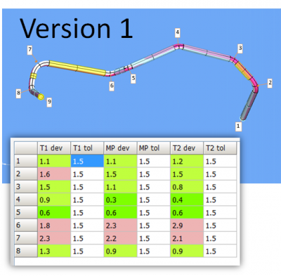
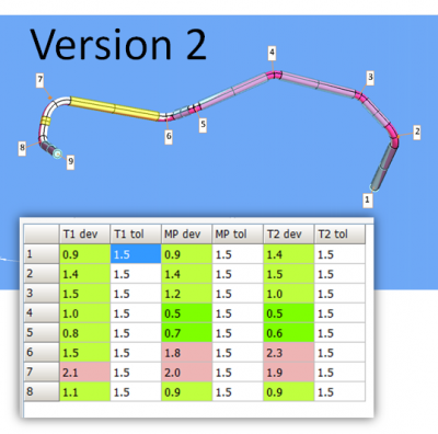
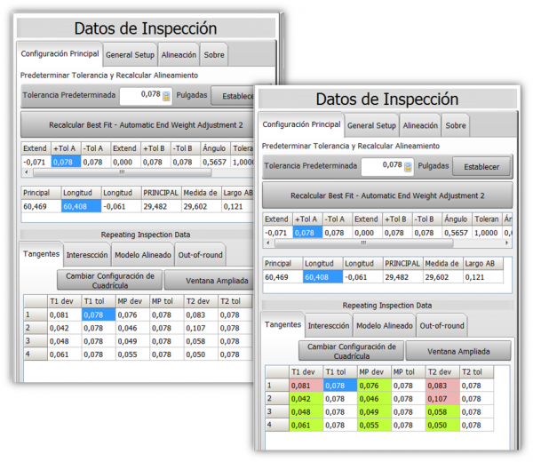
We're always happy to give you a feature that does more - and does more FASTER than before. This is one of those features. The alignments shown on the right are the results of the two different kinds of alignments now available in version 2.5. We used the same master/measured data. When qualifications are on the edge of the tolerance, then the new version 2 of Best Fit has a better chance of qualifying a tube.
|
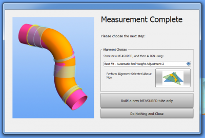
 IMPROVED: The MEASUREMENT COMPLETE Window is Redesigned for Simplicity
|
The Measurement Complete window is the window that displays when you finish measurements. It has been redesigned to make it even easier to use. |
 FIX: Floating Point Numbers with Commas
|
Previous versions of VTube had difficulty handling number systems that uses commas as a decimal symbol. |
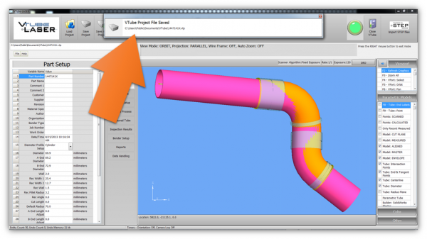
 NEW: Project File Save Notification Proves the Project Was Saved
|
Previous versions of VTube were quiet when you saved a project file. That made some of our customers understandably nervous. |
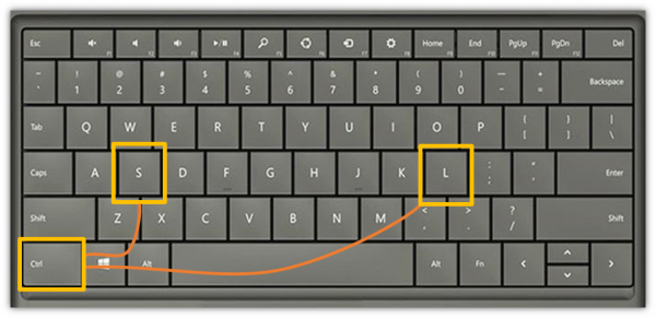
 NEW: HOT Keys Control-L (Load) and Control-S (Save) for VTube Project Files
|
These new hotkeys are a simple thing- but they'll make your life much easier if you're a hotkey user. (The new project save notification window described above will display every time you press CTRL-S.) |
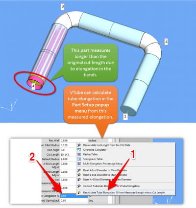
 NEW: CALCULATE TUBE ELONGATION PERCENTAGE FEATURE
|
Now VTube-LASER can calculate Tube Elongation Percentage by subtracting the current CUT LENGTH from the MEASURED LENGTH - then calculate the percentage by comparing that change to the total ARC LENGTHS in the measured tube. |
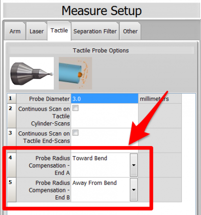
 ENHANCEMENT and FIX: The PROBE RADIUS COMPENSATION Feature
|
If you measure the ends of tubes with the ball probe, and the probe radius compensation directions at either end are ever different, then this update is critical for you. CHANGED CAPTIONS IN SETUP |
 FIX: Transfluid XYZ Output (BKT File) Repairs
|
This feature allows you to output new XYZ data to the bender from inside VTube-STEP (which is part of VTube-LASER). |
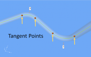
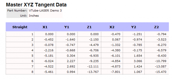
 NEW: Tangent Point Reports
|
VTube can now output Tangent Point reports. |
 NEW: Newport News Shipbuilding Data Import
|
VTube can now import Newport News Shipbuilding data for shipbuilding applications. |
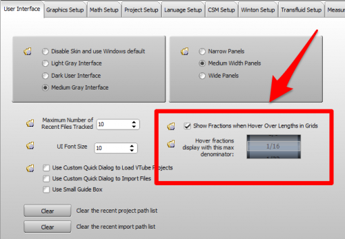
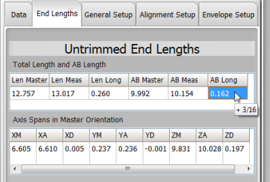
 NEW: Hover Fractions
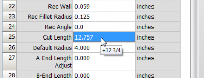
VTube can now show the fractional version of any distance in the main grids in a hint box.
The feature is switched on in the User Interface tab inside the System Options menu. The maximum denominator can be set to 1/2, 1/4, 1/8, 1/16, 1/32, or 1/64. The default value is 1/16.
Click on any length field and hover to show the fractional hint.
 OTHER CHANGES
- When decreasing the point count in VTube-LASER without clearing the project, the reports would continue to show the previous expanded point count for the Tangent Points and Midpoints list. This has been fixed.
- The Overbend Calculator incorrectly swapped the Proportional and Fixed values in the springback formula for the springback grid inside the calculator. This has been fixed.
- The Springback compensation, when enabled, was not calculated correctly in outgoing Supravision files. This has been fixed.
- The End B Length Adjustment feature would not draw the tube diameter correctly when set to more than or less than 0. This has been fixed.
- The default straight tolerance value is now used to automatically fill in tolerance fields in the grids with tolerances. (Previous versions would always use 0.039" or 1 mm for the tolerances in inspection grids.)
Other Pages
- Back to VTube-STEP
- Back to VTube Software Updates (for LASER Mode)
- Back to VTube-LASER
- See VTube Language Editor

