Difference between revisions of "BendPro"
(→G1 Version Communications Rules) |
|||
| (178 intermediate revisions by one user not shown) | |||
| Line 1: | Line 1: | ||
| − | [[image:BendPro-G2. | + | <table cellpadding="30"> |
| + | <tr valign=top> | ||
| + | <td width="400"> | ||
| + | BendPro is a popular bender software package used by multiple bender OEMs in the industry. There are two versions commonly used: G1 and G2 | ||
| + | <br><br> | ||
| + | __NOTOC__ | ||
| + | </td> | ||
| + | <td> | ||
| + | [[image:BendPro-G2.png|300px]]<br> | ||
| + | </td> | ||
| + | </tr> | ||
| + | </table> | ||
| − | |||
| + | = 1 - About BendPro Manual Data File Import = | ||
| − | BendPro | + | |
| + | BendPro operators can import Supravision files directly into the part database on the control. The operator enters the FILE window, then opens a dialog and selects the Supravision file to import. | ||
| + | |||
| + | This allows our software to act as a remote programmer for bender data on a BendPro. | ||
| + | |||
| + | VTube-LASER and VTube-STEP can build [[Supravision]] files from STEP and IGES models. | ||
| + | |||
| + | * [[VTube-STEP]] | ||
| + | * [[VTube-LASER]] | ||
<br><br> | <br><br> | ||
| − | |||
| − | |||
| + | == G1 Manual File Import: Supravision Type == | ||
| − | + | Follow these steps to import Supravision files: | |
| + | [[image:G1MainScreen_EditPart_Button.png|600px]]<br><br> | ||
| + | [[image:G1PartEditorScreen_ImportPartNumber_Button.png|600px]]<br><br> | ||
| + | [[image:G1PartEditorScreen_FileType_Supravision.png|600px]]<br><br> | ||
| − | + | <br><br><br> | |
| − | + | = 2 - About BendPro Measuring Center Communications = | |
| − | |||
| − | |||
| + | BendPro uses the '''Supravision Network''' protocol for communications. Communications are straight-forward, efficient, and very fast. | ||
| − | + | The BendPro can be setup to communicate with HEXAGON or FARO ScanArms running our [[VTube-LASER]] software | |
| + | <br><br> | ||
| − | ==== | + | ==How to Check if BendPro G2 Measuring Center Communications Are Possible On Your Bender Control== |
| + | |||
| + | ====Utilities - Measure Machine Interface==== | ||
<table cellpadding="30"> | <table cellpadding="30"> | ||
| + | |||
<tr valign=top> | <tr valign=top> | ||
<td width=500> | <td width=500> | ||
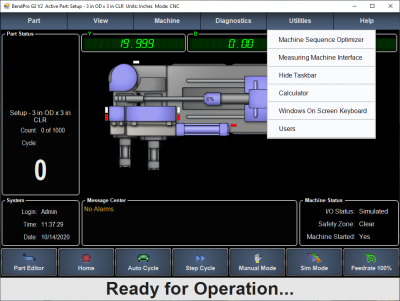
| − | The Supravision link is sold by | + | The Supravision link is sold by Current Tech as an option that can be enabled.<br><br> |
| − | + | It's important to verify that this option is switched on when discovering if a BendPro G2 is ready for communication. Click on the '''Utilities''' pulldown menu...<br><br> | |
| − | + | ||
</td> | </td> | ||
<td> | <td> | ||
| − | [[image: | + | [[image:G2V2_BenderScreen_UtilitiesMeasuringCenter.png|400px]]<br><br> |
| − | + | ||
</td> | </td> | ||
</tr> | </tr> | ||
| + | |||
| + | <tr valign=top> | ||
| + | <td width=500> | ||
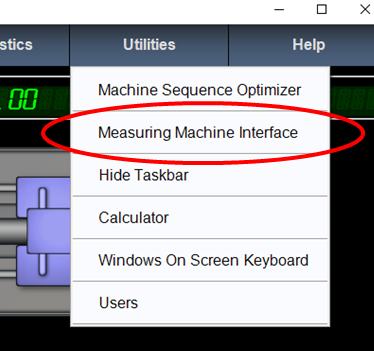
| + | ...then click on the '''Measuring Machine Interface''' option.<br><br> | ||
| + | </td> | ||
| + | <td> | ||
| + | [[image:bendpro_measuring_machine_interface_menuitem.png|400px]]<br><br> | ||
| + | </td> | ||
| + | </tr> | ||
| + | |||
| + | |||
| + | <tr valign=top> | ||
| + | <td width=500> | ||
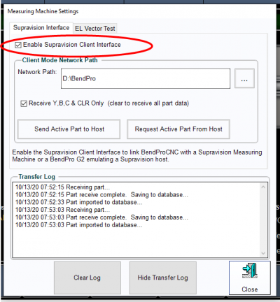
| + | If the '''Enable Supravision Client Interface Option''' checkbox will allow you to check the box, then your bender has communication capability.<br><br> | ||
| + | </td> | ||
| + | <td> | ||
| + | [[image:bendpro_supravisioninterface_menu_allow_enableSupravisionClientInterface.png|400px]] | ||
| + | </td> | ||
| + | </tr> | ||
| + | |||
</table> | </table> | ||
| + | |||
| + | ==How to Check if BendPro G1 Communications is Possible on Your Bender Control== | ||
====G1 Version==== | ====G1 Version==== | ||
| Line 45: | Line 89: | ||
<tr valign=top> | <tr valign=top> | ||
<td width=500> | <td width=500> | ||
| − | Verify that this option is switched on when discovering if a BendPro G1 is ready for communication | + | =====Edit Part Button===== |
| − | + | Verify that this option is switched on when discovering if a BendPro G1 is ready for communication.<br><br> | |
| − | If you | + | '''If you are able to open the BendPro to Supravision Link window then your software has communication capability.'''<br><br> |
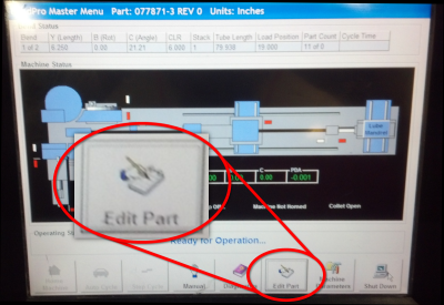
| + | Click on Edit Part button in the main screen:<br> | ||
</td> | </td> | ||
<td> | <td> | ||
| − | [[image: | + | [[image:bendpro_g1_editpart.png|400px]]<br><br> |
</td> | </td> | ||
</tr> | </tr> | ||
| + | |||
| + | |||
| + | <tr valign=top> | ||
| + | <td width=500> | ||
| + | |||
| + | =====Measure Machine Button===== | ||
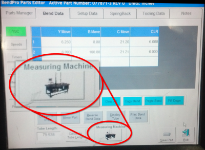
| + | Try pressing the Measure Machine button:<br></td> | ||
| + | <td> | ||
| + | [[image:bendpro_g1_measuremachine.png|400px]]<br><br> | ||
| + | </td> | ||
| + | </tr> | ||
| + | |||
| + | |||
| + | <tr valign=top> | ||
| + | <td width=500> | ||
| + | |||
| + | =====BendPro to Supravison Link Screen===== | ||
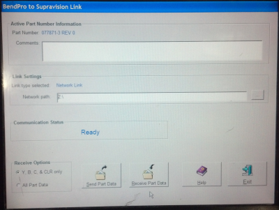
| + | '''If you can see this BendPro window - then you have communications capabilities on your control.'''<br><br>You can edit the network path for the protocol and also choose and set some communications options.<br> | ||
| + | </td> | ||
| + | <td> | ||
| + | [[image:g1_supravisionscreen.png|400px]]<br> | ||
| + | </td> | ||
| + | </tr> | ||
| + | |||
</table> | </table> | ||
| − | ==Communications | + | ==How to Setup and Use Communications with BendPro G2== |
====G2 Version Communications Setup==== | ====G2 Version Communications Setup==== | ||
| Line 65: | Line 134: | ||
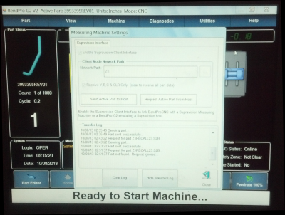
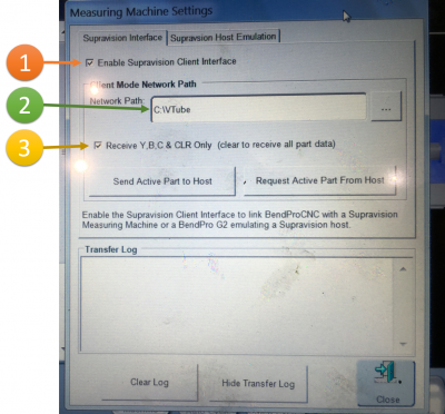
* Put a check in the checkbox to enable communications.<br><br> | * Put a check in the checkbox to enable communications.<br><br> | ||
* Setup the path that Supravision Network will use for communications.<br><br> | * Setup the path that Supravision Network will use for communications.<br><br> | ||
| − | * Use the Machine Parameters / General Options to setup the correct bender number.<br><br> | + | * Use the Machine Parameters / General Options to setup the correct bender number. If the bender number does not match the bender number used at the measuring center, then communications will not occur.<br><br> |
* The G2 user interface does not need to be in the Measuring Center menu to communicate. However, that menu includes a log that displays the time of the last data transmission. If there are errors, then this is where they will be listed. So it is beneficial to change to that menu before communications.<br><br> | * The G2 user interface does not need to be in the Measuring Center menu to communicate. However, that menu includes a log that displays the time of the last data transmission. If there are errors, then this is where they will be listed. So it is beneficial to change to that menu before communications.<br><br> | ||
| + | * It is important to ENABLE the "Receive Y, B, C & CLR Only" option, or the BendPro's setup may be changed in ways that make the bender not run at all.<br><br> | ||
| + | This is a closeup of the G2 log after communications:<br> | ||
| + | [[image:G2V2_UtilitiesMeasuringCenter_LogAfterCommunications.png|400px]] | ||
</td> | </td> | ||
<td> | <td> | ||
| − | [[image:G2V2_MeasuringMachineSettings.png|400px]] | + | [[image:G2V2_MeasuringMachineSettings.png|400px]]<br><br> |
| + | [[image:bendpro_supravisioninterface_menu_highlighted_setup.png|400px]] | ||
</td> | </td> | ||
</tr> | </tr> | ||
</table> | </table> | ||
| + | |||
| + | ====G2 Version - DISABLE Host Emulation==== | ||
| + | |||
| + | <table cellpadding="30"> | ||
| + | <tr valign=top> | ||
| + | <td width=500> | ||
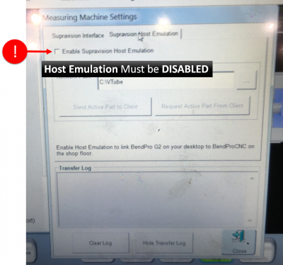
| + | Some G2 controls have a '''Host Emulation''' tab menu.<br><br> | ||
| + | It is critical that you are sure that the '''host emulation''' mode is '''disabled''' - or standard communications will not work properly.<br><br> | ||
| + | Host emulation mode enables BendPro to act like the measuring center side of the communication. If both '''Host Emulation''' and '''Client Interface'' are switched on at the same time, then they interfere with each other. | ||
| + | </td> | ||
| + | <td> | ||
| + | [[image:G2V2_HostEmulationDisabled.png|400px]] | ||
| + | </td> | ||
| + | </tr> | ||
| + | </table> | ||
| + | |||
====G2 Version Communications Rules==== | ====G2 Version Communications Rules==== | ||
| Line 81: | Line 170: | ||
The following rules apply for communication using the Supravision Network protocol: | The following rules apply for communication using the Supravision Network protocol: | ||
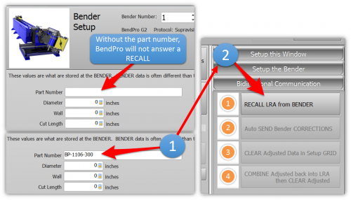
| − | * To correct an existing part in the bender, the part must be saved in the BendPro database, and must be the active part.<br><br> | + | * To RECALL data from BendPro, the measuring center '''must ask for the part with the correct part name''' - or BendPro will not answer.<br><br> |
| − | * <b>The part number must have no spaces.</b> The G2 controls will parse the part number so that all letters after the first space are deleted. For example: "01234 REV0" will be trimmed to "01234". If this new part number does not exist, then the G2 control will ask if you want to import a new part.<br><br> | + | * To correct an ''existing'' part in the bender, the part must be saved in the BendPro database, and must be the active part.<br><br> |
| − | * Changing the first straight length will also change the START position for the first bend. | + | * <b>The part number must have no spaces.</b> The G2 controls will parse the part number so that all letters after the first space are deleted. For example:<br> |
| + | <pre>"01234 REV0"</pre> will be trimmed to "01234". If this new part number does not exist, then the G2 control will ask if you want to import a new part.<br><br> | ||
| + | * To send a NEW part to the bender, the part number must NOT already be in the database.<br><br> | ||
| + | * Changing the first straight length will also change the START position for the first bend. If you are using VTube-LASER to correct the bender, and don't want the first or the last straight lengths to change, then manually set the first adjustment to zero in the Bender Setup menu before sending a correction. | ||
</td> | </td> | ||
<td> | <td> | ||
| + | [[image:G2V2_MustEnterPartNumber.png|500px]] | ||
</td> | </td> | ||
| Line 92: | Line 185: | ||
<br><br> | <br><br> | ||
| − | ==Communications | + | ==How to Setup and Use Communications on the BendPro G1== |
| − | + | ===G1 Version Communications Setup=== | |
<table cellpadding="30"> | <table cellpadding="30"> | ||
<tr valign=top> | <tr valign=top> | ||
<td width=500> | <td width=500> | ||
| − | * | + | * Starting from the main screen, press Edit Part button on the bottom of the screen.<br><br> |
* Press the Measuring Machine button to enter the Supravision Network screen (see the image on the right).<br><br> | * Press the Measuring Machine button to enter the Supravision Network screen (see the image on the right).<br><br> | ||
* Setup the path that Supravision Network will use for communications.<br><br> | * Setup the path that Supravision Network will use for communications.<br><br> | ||
| − | * Use the Machine Parameters / General Options to setup the correct bender number.<br><br> | + | * Use the Machine Parameters / General Options to setup the correct bender number. If the bender number does not match the bender number used at the measuring center, then communications will not occur.<br><br> |
</td> | </td> | ||
<td> | <td> | ||
| − | [[image: | + | [[image:g1_supravisionscreen.png|400px]]<br> |
</td> | </td> | ||
</tr> | </tr> | ||
</table> | </table> | ||
| − | + | ===G1 Version Communications Rules=== | |
<table cellpadding="30"> | <table cellpadding="30"> | ||
| Line 116: | Line 209: | ||
<td width=500> | <td width=500> | ||
The following rules apply for communication using the Supravision Network protocol: | The following rules apply for communication using the Supravision Network protocol: | ||
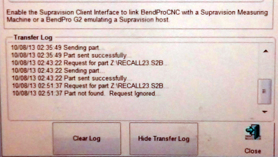
| − | * Unlike the G2 user interface, the G1 | + | * Unlike the G2 user interface, the G1 Supravision window needs to be displayed during communications. The menu includes a single line that displays if communications works.<br><br> |
| − | * | + | * Spaces are allowed in the part number - <b>but NOT recommended</b>. If the exact number of spaces don't match, then the communication will fail. It is difficult to differentiate between one space and two spaces, and the G1 can have spaces AFTER the part name - which is not discernable until you enter the keyboard to edit the name. Recommendation: Replace the spaces with underscores.<br><br> |
| + | * AFTER a send from the measuring center to the bender it is necessary for the operator to walk out to the bender and press the RECEIVE PART DATA button.<br><br>For VTube-LASER '''SEND''', there is no timeout. For Supravision or DOCS, if the timeout occurs before the operator arrives at the bender to press the button, then DOCS and Supravision will delete the data file - and the communications will fail.<br><br>If there are errors, then this is where they will be listed.<br><br> | ||
* To correct an existing part in the bender, the part must be saved in the BendPro database, and must be the active part.<br><br> | * To correct an existing part in the bender, the part must be saved in the BendPro database, and must be the active part.<br><br> | ||
| − | * | + | * To send a NEW part to the bender, the part number must NOT already be in the database.<br><br> |
| − | * Changing the first straight length will also change the START position for the first bend. | + | * Changing the first straight length will also change the START position for the first bend. If you are using VTube-LASER to correct the bender, and don't want the first or the last straight lengths to change, then manually set the first adjustment to zero in the Bender Setup menu before sending a correction. |
</td> | </td> | ||
<td> | <td> | ||
| − | This image | + | This is the Communications Status before any communications:<br> |
| − | [[image: | + | [[image:G1_ComStatusReady.png|400px]]<br><br> |
| + | This is the Communications Status after communications are sent to the measuring center after the measuring center recalled data:<br> | ||
| + | [[image:G1_ComStatusSuccessfullySent.png|400px]]<br><br> | ||
| + | The G1 control requires you to press RECEIVE PART DATA button after sending data from the measuring center.<Br> | ||
| + | [[image:G1_ReceivePartDataButton.png|400px]]<br><br> | ||
<br> | <br> | ||
This image shows the message after the part has been received:<Br> | This image shows the message after the part has been received:<Br> | ||
| − | [[image: | + | [[image:G1_ComStatusSucessfullyReceived.png|400px]]<br> |
</td> | </td> | ||
</tr> | </tr> | ||
| Line 133: | Line 231: | ||
<br><br> | <br><br> | ||
| + | |||
| + | ==General Communications Notes== | ||
| + | |||
| + | ===Part Note Length Limitation=== | ||
| + | |||
| + | <table cellpadding="30"> | ||
| + | <tr valign=top> | ||
| + | <td width=500> | ||
| + | BendPro operators can easily type in a part note that is very long: | ||
| + | |||
| + | * Supravsion (older software on a ROMER or MM5000 measuring center) will shutdown without warning if it receives a part note with more than 95 characters.<br><br> | ||
| + | * VTube-LASER can handle any part note length. | ||
| + | |||
| + | </td> | ||
| + | <td> | ||
| + | </td> | ||
| + | </tr> | ||
| + | </table> | ||
| + | |||
| + | ===Speed and Centerline Radius Fields Observed=== | ||
| + | <table cellpadding="30"> | ||
| + | <tr valign=top> | ||
| + | <td width=500> | ||
| + | * BendPro returns the YBC axis SPEEDS in the Supravision data transfer. This data should be observed and returned from any Benderlink system - or the speeds may be reset to a new value during the next correction. <b>For this reason, it is a good idea to always perform a RECALL before SENDING data corrections to a BendPro control.</b><br><br> | ||
| + | * BendPro will use the incoming Ceterline Radius values in the Supravision transmission (rather than the values in the tool page). This data should be observed and returned from any Benderlink system - or the radii may be reset to the new incoming vale during the next correction. <b>For this reason, it is a good idea to always perform a RECALL before SENDING data corrections to a BendPro control.</b> | ||
| + | </td> | ||
| + | <td> | ||
| + | </td> | ||
| + | </tr> | ||
| + | </table> | ||
| + | |||
| + | ===Non-Bending YBC Row Avoidance Moves=== | ||
| + | <table cellpadding="30"> | ||
| + | <tr valign=top> | ||
| + | <td width=500> | ||
| + | BendPro operators will sometimes use non-bending rows in the YBC data to enable special avoidance moves.<br><br> | ||
| + | *Supravision and DOCs cannot handle data with avoidance moves inserted in the YBC data. It is necessary to make manual corrections in these cases.<br><br> | ||
| + | * VTube-LASER uses a data mapping feature to allow for any number of non-bending rows. | ||
| + | </td> | ||
| + | <td> | ||
| + | </td> | ||
| + | </tr> | ||
| + | </table> | ||
| + | |||
| + | ===Handling Inverted Rotations=== | ||
| + | <table cellpadding="30"> | ||
| + | <tr valign=top> | ||
| + | <td width=500> | ||
| + | * DOCs software will sometimes invert rotations (to move in the opposite direction) - especially when making rotation corrections around the 180 degree area. Be aware of this and be prepared to reset any rotation that is moving in the wrong direction.<br><br> | ||
| + | * Supravision observes and maintains the rotation direction found at the bender.<br><br> | ||
| + | * VTube-LASER allows operators to check an Invert checkbox to invert any rotation corrected to the opposite direction. Operators of VTube should observe any rotation that is close to 180 degrees to check for the possibility for the need for inversion. This gives operators complete control over the rotation direction during correction.</td> | ||
| + | <td> | ||
| + | </td> | ||
| + | </tr> | ||
| + | </table> | ||
| + | |||
| + | == How to Recall Data from BendPro to Become Master Data == | ||
| + | It is possible to recall data from the BendPro to make it the MASTER data at VTube-LASER using these steps. Be sure that the BendPro is ready for communications before you perform a recall. | ||
| + | |||
| + | ===1 - Enable Communications At BendPro=== | ||
| + | |||
| + | [[image:bendpro_supravisioninterface_menu_highlighted_setup.png|400px]] | ||
| + | <br><br> | ||
| + | |||
| + | ===2 - Use the VTube-LASER Bender Setup Screen to Recall Master XYZ=== | ||
| + | |||
| + | [[image:recallbenderxyztomasterxyz.png|800px]]<br><br> | ||
| + | |||
| + | *Select the bender number in Bend Setup. | ||
| + | *Enter the part number to recall. This name must match a name in the BendPro database. | ||
| + | *Click on Setup this Window. | ||
| + | *Click on RECALL Bender XYZ to Master XYZ. | ||
| + | <br><br> | ||
| + | |||
| + | ===3 - VTube-LASER will Wait for the Data=== | ||
| + | [[image:recallbenderxyztomasterxyz2.png|800px]] | ||
| + | <br><br> | ||
| + | |||
| + | ===4 - BendPro will Answer with Data=== | ||
| + | |||
| + | If the part exists at the BendPro, then it will answer with the part and VTube-LASER will display this message: | ||
| + | <br><br> | ||
| + | [[image:recallbenderxyztomasterxyz3.png|800px]] | ||
| + | |||
| + | <br><br> | ||
| + | |||
| + | |||
| + | ===5 - VTube-LASER Will Close the Bender Setup Screen and Display the MASTER Data=== | ||
| + | [[image:recallbenderxyztomasterxyz4.png|800px]] | ||
| + | |||
| + | If you do not see an image, then be sure that Model: MASTER has a checkmark and then press F2-F3. Also, you can check in the Master Tube menu for new coordinates. | ||
| + | <br><br> | ||
| + | |||
| + | ===6 - Save the new VTube-LASER Project File=== | ||
| + | [[image:recallbenderxyztomasterxyz5.png|800px]] | ||
| + | <br><br> | ||
| + | <br><br> | ||
| + | <br><br> | ||
| + | <br><br> | ||
| + | |||
| + | == How to Assign Default Options in BendPro G2 == | ||
| + | |||
| + | These steps allow you to set up BendPro Default Options for reuse when setting up new parts. | ||
| + | |||
| + | This feature of the BendPro Part Editor is essentially everything about a part other than part geometries - information such as the Tools information (CD and PD lengths, collet depth, etc.), Load and Unload information, Enables, Springback, etc. The Setup Tables and the Default Table are easy to get to and use. | ||
| + | |||
| + | [[image:bendprodefaultoptions.jpg]] | ||
| + | |||
| + | |||
| + | These 3 selections are associated with the default table: | ||
| + | |||
| + | * If Load From Default Table is selected, the default table information is applied to the Active Part. | ||
| + | * If Save to Default Table is selected, the current settings of the Active Part are saved to the default table. | ||
| + | * Edit Setup Table edits the current default table. | ||
| + | |||
| + | [[image:bendprodefaultoptions2.jpg]] | ||
== Other == | == Other == | ||
Latest revision as of 21:44, 18 April 2023
|
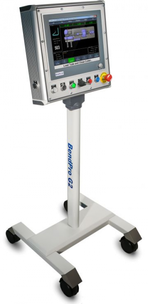
BendPro is a popular bender software package used by multiple bender OEMs in the industry. There are two versions commonly used: G1 and G2
|
1 - About BendPro Manual Data File Import
BendPro operators can import Supravision files directly into the part database on the control. The operator enters the FILE window, then opens a dialog and selects the Supravision file to import.
This allows our software to act as a remote programmer for bender data on a BendPro.
VTube-LASER and VTube-STEP can build Supravision files from STEP and IGES models.
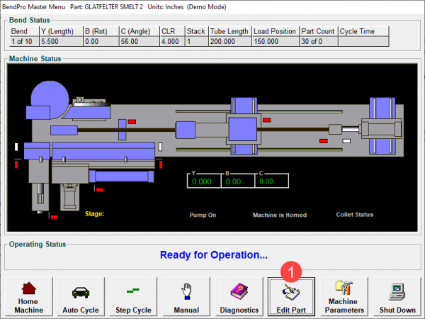
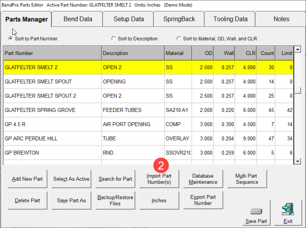
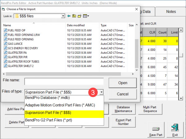
G1 Manual File Import: Supravision Type
Follow these steps to import Supravision files:
2 - About BendPro Measuring Center Communications
BendPro uses the Supravision Network protocol for communications. Communications are straight-forward, efficient, and very fast.
The BendPro can be setup to communicate with HEXAGON or FARO ScanArms running our VTube-LASER software
How to Check if BendPro G2 Measuring Center Communications Are Possible On Your Bender Control
Utilities - Measure Machine Interface
|
The Supravision link is sold by Current Tech as an option that can be enabled. |
|
|
...then click on the Measuring Machine Interface option. |
|
|
If the Enable Supravision Client Interface Option checkbox will allow you to check the box, then your bender has communication capability. |
How to Check if BendPro G1 Communications is Possible on Your Bender Control
G1 Version
Edit Part ButtonVerify that this option is switched on when discovering if a BendPro G1 is ready for communication. |
|
Measure Machine ButtonTry pressing the Measure Machine button: |
|
BendPro to Supravison Link ScreenIf you can see this BendPro window - then you have communications capabilities on your control. |
How to Setup and Use Communications with BendPro G2
G2 Version Communications Setup
|
G2 Version - DISABLE Host Emulation
|
Some G2 controls have a Host Emulation tab menu. |
G2 Version Communications Rules
|
The following rules apply for communication using the Supravision Network protocol:
"01234 REV0"will be trimmed to "01234". If this new part number does not exist, then the G2 control will ask if you want to import a new part.
|
How to Setup and Use Communications on the BendPro G1
G1 Version Communications Setup
|
G1 Version Communications Rules
General Communications Notes
Part Note Length Limitation
|
BendPro operators can easily type in a part note that is very long:
|
Speed and Centerline Radius Fields Observed
|
Non-Bending YBC Row Avoidance Moves
|
BendPro operators will sometimes use non-bending rows in the YBC data to enable special avoidance moves.
|
Handling Inverted Rotations
|
How to Recall Data from BendPro to Become Master Data
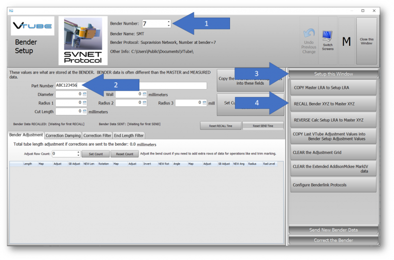
It is possible to recall data from the BendPro to make it the MASTER data at VTube-LASER using these steps. Be sure that the BendPro is ready for communications before you perform a recall.
1 - Enable Communications At BendPro
2 - Use the VTube-LASER Bender Setup Screen to Recall Master XYZ
- Select the bender number in Bend Setup.
- Enter the part number to recall. This name must match a name in the BendPro database.
- Click on Setup this Window.
- Click on RECALL Bender XYZ to Master XYZ.
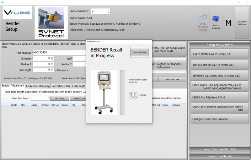
3 - VTube-LASER will Wait for the Data
4 - BendPro will Answer with Data
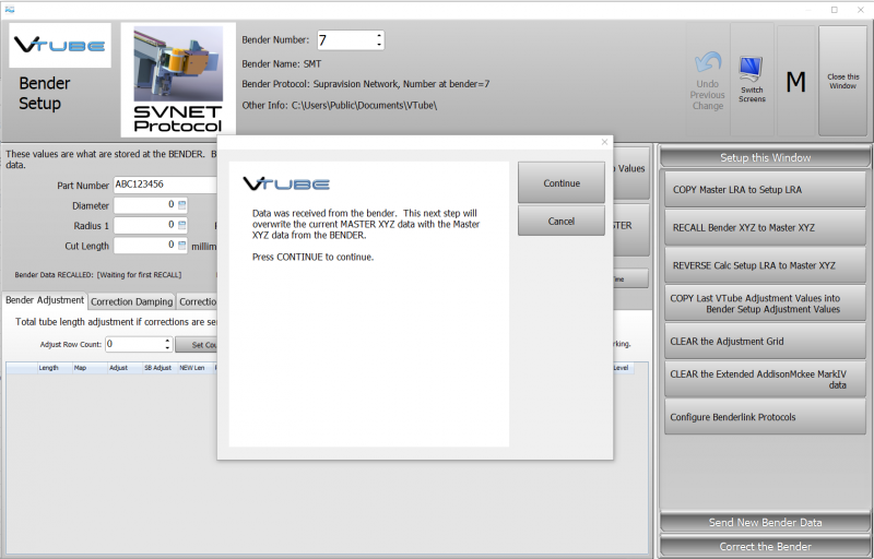
If the part exists at the BendPro, then it will answer with the part and VTube-LASER will display this message:
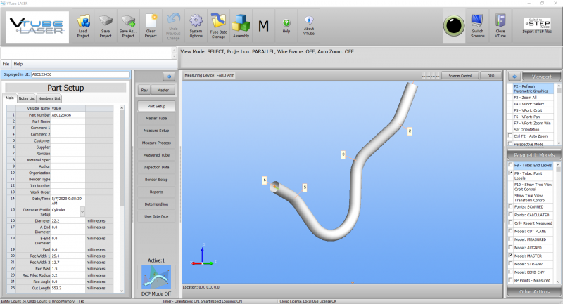
5 - VTube-LASER Will Close the Bender Setup Screen and Display the MASTER Data
If you do not see an image, then be sure that Model: MASTER has a checkmark and then press F2-F3. Also, you can check in the Master Tube menu for new coordinates.
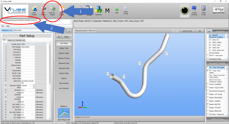
6 - Save the new VTube-LASER Project File
How to Assign Default Options in BendPro G2
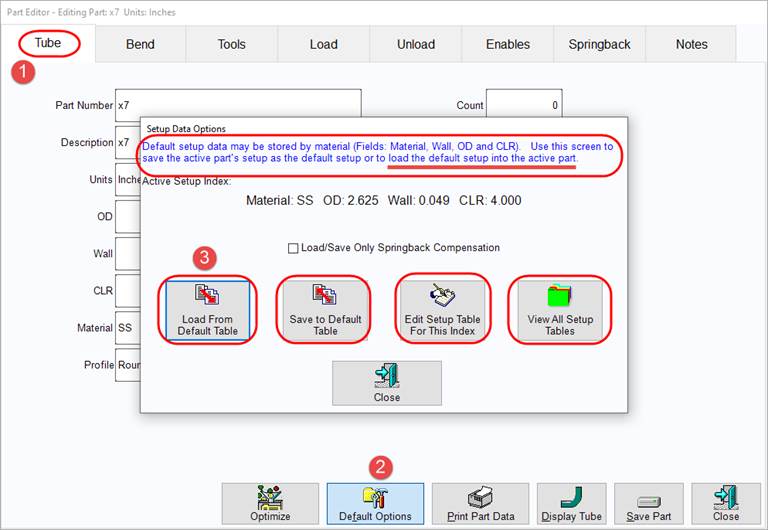
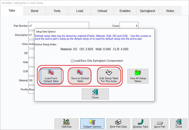
These steps allow you to set up BendPro Default Options for reuse when setting up new parts.
This feature of the BendPro Part Editor is essentially everything about a part other than part geometries - information such as the Tools information (CD and PD lengths, collet depth, etc.), Load and Unload information, Enables, Springback, etc. The Setup Tables and the Default Table are easy to get to and use.
These 3 selections are associated with the default table:
- If Load From Default Table is selected, the default table information is applied to the Active Part.
- If Save to Default Table is selected, the current settings of the Active Part are saved to the default table.
- Edit Setup Table edits the current default table.
Other
- See also VTube-LASER
- See also Benderlink for FARO
