Difference between revisions of "Revision: Benderlink for BLM 5.3"
(→25px NEW - Switch for "Do Not Allow Measuring Center to Change End Lengths") |
(→25px NEW - Click on LEDs to Toggle to Measuring Center Monitoring) |
||
| (4 intermediate revisions by one user not shown) | |||
| Line 21: | Line 21: | ||
| − | ===[[image:Check.jpg|25px]] NEW - | + | ===[[image:Check.jpg|25px]] NEW - Communications Transfers No Longer Change the BLM Radius Levels=== |
<table width=700> | <table width=700> | ||
<tr> | <tr> | ||
<td width=300> | <td width=300> | ||
| − | + | Setting or changing BLM radius levels could easily cause radius level mix ups during corrections loops. The radius levels are no longer touched or changed during transfer. <br><br> | |
| − | + | Not setting the radius levels is no problem - since corrections loops targets the LRA data only anyway. | |
</td> | </td> | ||
<td width=400> | <td width=400> | ||
| − | [[image: | + | [[image:blinkblm_electric_verticalshift.png|400px]] |
</td> | </td> | ||
</tr> | </tr> | ||
| Line 37: | Line 37: | ||
<br><br> | <br><br> | ||
| − | ===[[image:Check.jpg|25px]] NEW - | + | ===[[image:Check.jpg|25px]] NEW - Switch for "Do Not Allow Measuring Center to Change End Lengths"=== |
<table width=700> | <table width=700> | ||
<tr> | <tr> | ||
<td width=300> | <td width=300> | ||
| − | + | During CORRECTION of parts with extra material on the ends, it is helpful to not allow the end lengths to change. This keeps the carriage in approximately the same start position even after corrections are applied.<br><br> | |
| − | + | This version of Benderlink now includes this checkbox switch to turn this feature on or off. | |
</td> | </td> | ||
<td width=400> | <td width=400> | ||
| − | [[image: | + | [[image:blinkblm_donotallowmeasuringcenterchangeendlengths.png|400px]] |
</td> | </td> | ||
</tr> | </tr> | ||
| Line 53: | Line 53: | ||
<br><br> | <br><br> | ||
| − | ===[[image:Check.jpg|25px]] | + | ===[[image:Check.jpg|25px]] ENHANCED - The Communications Protocol is Enhanced for LASERVISION Windows Version=== |
<table width=700> | <table width=700> | ||
<tr> | <tr> | ||
<td width=300> | <td width=300> | ||
| − | + | The internal communications logic was enhanced to work properly with Windows versions of LASERVISION. (It already worked with DOS versions of LASERVISION.)<br><br> | |
| − | + | ||
</td> | </td> | ||
<td width=400> | <td width=400> | ||
| − | [[image: | + | [[image:vector_tube_data_center.jpg|400px]]<br> |
</td> | </td> | ||
</tr> | </tr> | ||
| Line 69: | Line 68: | ||
<br><br> | <br><br> | ||
| − | ===[[image:Check.jpg|25px]] | + | |
| + | ===[[image:Check.jpg|25px]] NEW - Large Green LED to Show Measuring Center Monitoring=== | ||
<table width=700> | <table width=700> | ||
<tr> | <tr> | ||
<td width=300> | <td width=300> | ||
| − | + | A new larger green LED port indicator to show that Benderlink is monitoring for measuring center communications is added to the interface.<br><br> | |
| + | It is also possible to click on the LED to toggle the measuring center monitor state. | ||
</td> | </td> | ||
<td width=400> | <td width=400> | ||
| − | [[image: | + | [[image:benderlinkblm_v5.3_large_led.png|400px]] |
</td> | </td> | ||
</tr> | </tr> | ||
| Line 83: | Line 84: | ||
</table> | </table> | ||
<br><br> | <br><br> | ||
| + | |||
===[[image:Check.jpg|25px]] NEW - Click on LEDs to Toggle to Measuring Center Monitoring=== | ===[[image:Check.jpg|25px]] NEW - Click on LEDs to Toggle to Measuring Center Monitoring=== | ||
| Line 99: | Line 101: | ||
<br><br> | <br><br> | ||
| − | ===[[image:Check.jpg|25px]] FIXED - Ping Port Confirmation Works in | + | ===[[image:Check.jpg|25px]] FIXED - Ping Port Confirmation Works in Windows 7, 8, 8.1, 10=== |
<table width=700> | <table width=700> | ||
| Line 115: | Line 117: | ||
<br><br> | <br><br> | ||
| − | ===[[image:Check.jpg|25px]] NEW - Message Warning for Ports That Cannot Open=== | + | ===[[image:Check.jpg|25px]] NEW - Message Warning for COM Ports That Cannot Open=== |
<table width=700> | <table width=700> | ||
<tr> | <tr> | ||
<td width=300> | <td width=300> | ||
| − | When a port to the measuring center cannot open, Benderlink now displays a message that a problem occurred. | + | When a COM port to the measuring center cannot open, Benderlink now displays a message that a problem occurred. |
</td> | </td> | ||
<td width=400> | <td width=400> | ||
| Line 129: | Line 131: | ||
</table> | </table> | ||
<br><br> | <br><br> | ||
| − | |||
| − | |||
==Other Pages== | ==Other Pages== | ||
Latest revision as of 22:03, 14 October 2015
Revision 5.3
|
- See Benderlink for BLM Customer Support Page to download the latest version.
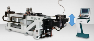
 NEW - Communications Transfers No Longer Change the BLM Radius Levels
|
Setting or changing BLM radius levels could easily cause radius level mix ups during corrections loops. The radius levels are no longer touched or changed during transfer. |
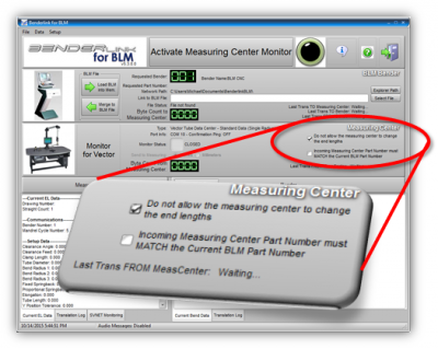
 NEW - Switch for "Do Not Allow Measuring Center to Change End Lengths"
|
During CORRECTION of parts with extra material on the ends, it is helpful to not allow the end lengths to change. This keeps the carriage in approximately the same start position even after corrections are applied. |
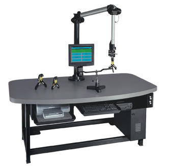
 ENHANCED - The Communications Protocol is Enhanced for LASERVISION Windows Version
|
The internal communications logic was enhanced to work properly with Windows versions of LASERVISION. (It already worked with DOS versions of LASERVISION.) |
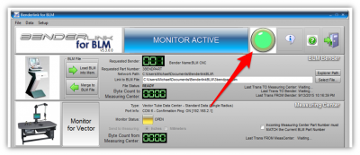
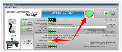
 NEW - Large Green LED to Show Measuring Center Monitoring
|
A new larger green LED port indicator to show that Benderlink is monitoring for measuring center communications is added to the interface. |
 NEW - Click on LEDs to Toggle to Measuring Center Monitoring
|
You can now click on either LED indicator to toggle monitoring for the measuring center commmands. |
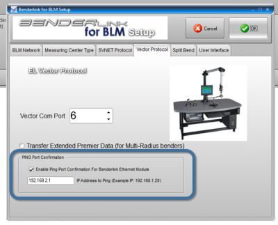
 FIXED - Ping Port Confirmation Works in Windows 7, 8, 8.1, 10
|
This feature allows Benderlink to ping for a serial device server before opening a virtual port. |
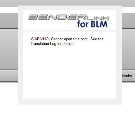
 NEW - Message Warning for COM Ports That Cannot Open
|
When a COM port to the measuring center cannot open, Benderlink now displays a message that a problem occurred. |
Other Pages
- Back to Benderlink for BLM Revisions
- Back to Benderlink for BLM
- Back to Benderlink
- Go to the main website Benderlink for BLM page
- About BLM Group USA


