Difference between revisions of "VTube-LASER v1.58"
| (28 intermediate revisions by one user not shown) | |||
| Line 13: | Line 13: | ||
__NOTOC__ | __NOTOC__ | ||
| − | + | ===[[image:Check.jpg|25px]] NEW: Construct Tube in 3D Space=== | |
| − | + | ||
| − | ===[[image:Check.jpg|25px]] NEW: | + | |
<table cellpadding=10> | <table cellpadding=10> | ||
<tr valign=top> | <tr valign=top> | ||
<td width=200> | <td width=200> | ||
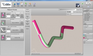
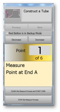
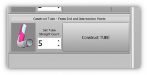
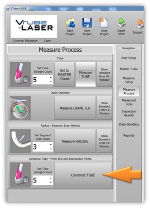
| − | + | Tube shapes can now be constructed by pointing the arm ball probe to the end points and intersection points.<br><br> | |
| + | This feature allows you to route a tube in 3D space. | ||
<br><br> | <br><br> | ||
| − | + | The feature is used by our customers to construct tube routes in a vehicle's engine compartment or under the car on a lift. | |
<br><br> | <br><br> | ||
| − | + | [[image:vtube-laser_1_58_constructtube_control.jpg|200px]] | |
</td> | </td> | ||
<td width=300> | <td width=300> | ||
| − | [[image:vtube- | + | [[image:vtube-laser_1_58_constructtube_closeup.jpg|300px]]<br><br> |
| + | [[image:vtube-laser_1_58_constructtube.jpg|300px]] | ||
</td> | </td> | ||
</tr> | </tr> | ||
</table> | </table> | ||
| − | |||
| − | |||
| − | |||
| − | |||
| − | |||
<table cellpadding=10> | <table cellpadding=10> | ||
<tr valign=top> | <tr valign=top> | ||
| − | <td width= | + | <td width=500> |
| − | + | The new Construct Tube Control (shown above) allows you to point to any location in space to designate an end point or an intersection point. It also allows you to increase the number of straights/points on-the-fly. This allows operators to change the number of points at any time during the measurement process. | |
| − | + | ||
| − | + | ||
</td> | </td> | ||
<td width=300> | <td width=300> | ||
| − | |||
| − | |||
| − | |||
| − | |||
| − | |||
| − | |||
| − | |||
| − | |||
</td> | </td> | ||
</tr> | </tr> | ||
| Line 58: | Line 43: | ||
<br><br> | <br><br> | ||
| − | ===[[image:Check.jpg|25px]] | + | ===[[image:Check.jpg|25px]] ENHANCED: Measure Tube Control - Decrease / Increase Button === |
<table cellpadding=10> | <table cellpadding=10> | ||
<tr valign=top> | <tr valign=top> | ||
<td width=200> | <td width=200> | ||
| − | + | Operators can now increase or decrease the number of straights to measure in the tube on-the-fly if necessary. The new Decrease/Increase buttons are inserted on the control. | |
<br><br> | <br><br> | ||
| − | The | + | The control also shows the total number of straights being measured. So now the control will read, for example "Straight 1 of 5" - rather than just "Straight 1." |
| − | + | ||
| − | + | ||
| − | + | ||
</td> | </td> | ||
<td width=300> | <td width=300> | ||
| − | [[image:vtube- | + | [[image:vtube-laser_1_58_measuretube_control.jpg|300px]] |
</td> | </td> | ||
</tr> | </tr> | ||
| Line 78: | Line 60: | ||
<br><br> | <br><br> | ||
| − | ===[[image:Check.jpg|25px]] | + | ===[[image:Check.jpg|25px]] NEW: Show SCANNED or CALCULATED Graphic Data Any Time=== |
| − | |||
<table cellpadding=10> | <table cellpadding=10> | ||
<tr valign=top> | <tr valign=top> | ||
<td width=200> | <td width=200> | ||
| − | + | VTube now allows operators to show or hide the orange scanned points or the large orange calculated end and intersection points at any time. | |
| − | + | ||
| − | + | ||
| − | + | ||
</td> | </td> | ||
<td width=300> | <td width=300> | ||
| + | [[image:vtube-laser_1_58_scanned_calculated_display.jpg|300px]]. | ||
</td> | </td> | ||
</tr> | </tr> | ||
| Line 96: | Line 75: | ||
<br><br> | <br><br> | ||
| − | ===[[image:Check.jpg|25px]] | + | ===[[image:Check.jpg|25px]] NEW: Auto Display SCANNED and CALCULATED=== |
| − | [[image:vtube- | + | [[image:vtube-laser_1_58_autodisplay_scanned_calculated.jpg|500px]] |
<table cellpadding=10> | <table cellpadding=10> | ||
<tr valign=top> | <tr valign=top> | ||
| − | <td width= | + | <td width=500> |
| − | + | The Draw Options feature is new to Measure Setup. You can select these two options if you want the SCANNED or the CALCULATED data to display or not during measurement. If both features are unchecked, then the tube measurement shows now realtime graphics data during measurement - like other measurement software. | |
</td> | </td> | ||
<td width=300> | <td width=300> | ||
| Line 111: | Line 90: | ||
<br><br> | <br><br> | ||
| − | ===[[image:Check.jpg|25px]] ENHANCED: | + | ===[[image:Check.jpg|25px]] ENHANCED: Highlighted Cylinder Fit Box During High Error=== |
| + | [[image:vtube-laser_1_58_cylinderfit_highlight.jpg|500px]] | ||
<table cellpadding=10> | <table cellpadding=10> | ||
<tr valign=top> | <tr valign=top> | ||
| − | <td width= | + | <td width=500> |
| − | The | + | The cylinder fit box highlights to YELLOW when it encounters a measurement in the tube that is outside the preprogrammed tolerance for cylinder fit. |
| − | + | ||
| − | + | ||
| − | + | ||
| − | + | ||
| − | + | ||
| − | + | ||
</td> | </td> | ||
<td width=300> | <td width=300> | ||
| − | |||
| − | |||
</td> | </td> | ||
</tr> | </tr> | ||
| Line 133: | Line 105: | ||
<br><br> | <br><br> | ||
| − | ===[[image:Check.jpg|25px]] | + | ===[[image:Check.jpg|25px]] Issues with this version fixed in next version=== |
<table cellpadding=10> | <table cellpadding=10> | ||
<tr valign=top> | <tr valign=top> | ||
| − | <td width= | + | <td width=500> |
| − | When | + | * When using tactile end-measure and laser straight measure in the same tube, the tactile measurements would never be offset by the ball radius. Don't mix tactile and laser measurements in this version or previous versions of VTube. |
| − | + | * See [[VTube-LASER v1.59]] | |
| − | + | ||
| − | + | ||
| − | + | ||
| − | + | ||
| − | + | ||
| − | + | ||
| − | + | ||
| − | + | ||
| − | + | ||
| − | + | ||
| − | + | ||
| − | + | ||
| − | + | ||
</td> | </td> | ||
<td width=300> | <td width=300> | ||
| Line 158: | Line 117: | ||
</tr> | </tr> | ||
</table> | </table> | ||
| − | |||
| − | |||
| − | |||
| − | |||
| − | |||
| − | |||
| − | |||
| − | |||
| − | |||
| − | |||
| − | |||
| − | |||
| − | |||
| − | |||
| − | |||
| − | |||
| − | |||
| − | |||
| − | |||
| − | |||
| − | |||
| − | |||
| − | |||
| − | |||
| − | |||
| − | |||
| − | |||
| − | |||
| − | |||
| − | |||
| − | |||
| − | |||
| − | |||
| − | |||
| − | |||
| − | |||
| − | |||
| − | |||
| − | |||
| − | |||
| − | |||
| − | |||
=Other Pages= | =Other Pages= | ||
*Back to [[VTube-LASER]] | *Back to [[VTube-LASER]] | ||
Latest revision as of 22:14, 21 February 2011
Revision 1.58Back to VTube-LASER |
 NEW: Construct Tube in 3D Space
|
The new Construct Tube Control (shown above) allows you to point to any location in space to designate an end point or an intersection point. It also allows you to increase the number of straights/points on-the-fly. This allows operators to change the number of points at any time during the measurement process. |
 ENHANCED: Measure Tube Control - Decrease / Increase Button
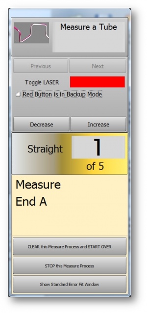
|
Operators can now increase or decrease the number of straights to measure in the tube on-the-fly if necessary. The new Decrease/Increase buttons are inserted on the control.
|
 NEW: Show SCANNED or CALCULATED Graphic Data Any Time
|
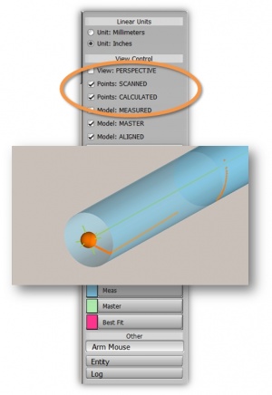
VTube now allows operators to show or hide the orange scanned points or the large orange calculated end and intersection points at any time. |
 NEW: Auto Display SCANNED and CALCULATED
|
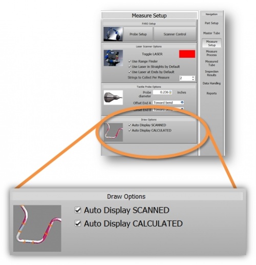
The Draw Options feature is new to Measure Setup. You can select these two options if you want the SCANNED or the CALCULATED data to display or not during measurement. If both features are unchecked, then the tube measurement shows now realtime graphics data during measurement - like other measurement software. |
 ENHANCED: Highlighted Cylinder Fit Box During High Error
|
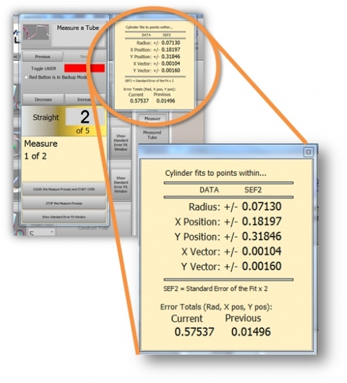
The cylinder fit box highlights to YELLOW when it encounters a measurement in the tube that is outside the preprogrammed tolerance for cylinder fit. |
 Issues with this version fixed in next version
|
Other Pages
- Back to VTube-LASER

