Difference between revisions of "What are Centerline Tangent Points and Why Are They Important in VTube-LASER?"
(→Why are Tangent Points Important in Qualifying Tube Shapes?) |
(→Tangent Point Deviations in the Inspection Data Grid) |
||
| Line 41: | Line 41: | ||
* T2d = Tangent 2 Deviation<br><br> | * T2d = Tangent 2 Deviation<br><br> | ||
| − | + | Note that the two end points are also included in the tangent charts are reports. They are an exception to the technical tangent definition given above because there is no bend attached to these points. But these points (T1d in straight 1, and T2d in the last straight) still have value in determining if the part is the correct shape, so it is convenient to include them in this chart and grid - even though they are not really tangents.<br><br> | |
The general rule is this: If the tangent points are within tolerance, then it follows that the shape of the part - based on the straights - fits well enough inside the tolerance envelope in order to qualify. In GD&T, this is often referred to as the centerline profile.<br><br> | The general rule is this: If the tangent points are within tolerance, then it follows that the shape of the part - based on the straights - fits well enough inside the tolerance envelope in order to qualify. In GD&T, this is often referred to as the centerline profile.<br><br> | ||
Revision as of 14:43, 23 April 2014
|
|
Why are Tangent Points Important in Qualifying Tube Shapes?
|
Centerline tangent points are important foundational points used to qualify the shape of the tube. Even so, they are not automatically understood. So this page describes why they are so important to measuring, and how to properly read the tangent deviation reports and charts.
|
Tangent Point Deviations in the Inspection Data Grid
|
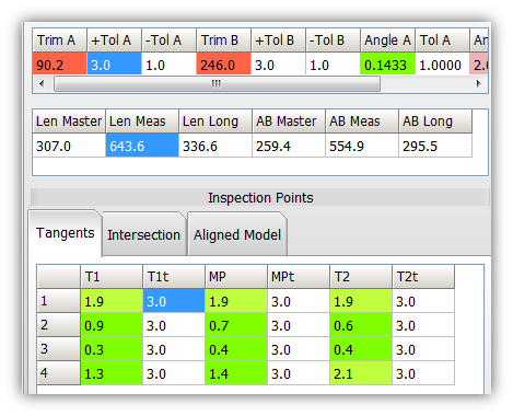
The Tangent chart is represented by a grid of straights for each row with tangent points and midpoints for each straight:
Note that the two end points are also included in the tangent charts are reports. They are an exception to the technical tangent definition given above because there is no bend attached to these points. But these points (T1d in straight 1, and T2d in the last straight) still have value in determining if the part is the correct shape, so it is convenient to include them in this chart and grid - even though they are not really tangents. The general rule is this: If the tangent points are within tolerance, then it follows that the shape of the part - based on the straights - fits well enough inside the tolerance envelope in order to qualify. In GD&T, this is often referred to as the centerline profile. |
The Same Data In Reports
|
The same tangent data can be shown in the reports like this. |
How to Understand the Tangent Data
How to Understand the End Point Deviations
Automatic Internal Trimming of End Points for Shape
|
Even though the end points are not tangents, we can still use them in the chart because they qualify the part the same way that tangent points do. |
Untrimmed End Points for Lengths
|
However, the end length is 90.2mm too long. In this application, the customer bent the part 90mm too long on purpose in order to give the bend arm clamp die enough material on the first straight to grip. Notice that, even though the part is significantly too long, the BEST FIT algorithm didn't use the actual measured end point in the alignment. The alignment was based on the trimmed point on the measured centerline that was nearest the master end point. So,in this case the part shape in space is qualified - but it needs trimming by 90.2mm to also qualify the end length (another critical qualifier). |
Other Pages
- Back to VTube-LASER


