Difference between revisions of "What are Centerline Tangent Points and Why Are They Important in VTube-LASER?"
(→The Inspection Data Grid) |
(→The Inspection Data Grid) |
||
| Line 26: | Line 26: | ||
* T2d = Tangent 2 Deviation<br><br> | * T2d = Tangent 2 Deviation<br><br> | ||
| − | Technically a tangent point is the point where any straight meets any bend. These are considered the best points for qualifying a tube shape because | + | Technically a tangent point is the point where any straight meets any bend. These are considered the best points for qualifying a tube shape because the are the points that most closely approximate the walls of a tube gauge.<br><br> |
| − | If the tangent points are within tolerance, then it follows that the shape of the part - based on the straights - fits well enough inside the | + | The two end points are an exception to the technical tangent definition given above. There is no bend attached to these points. But these points (T1d in straight 1, and T2d in the last straight) still have value in determining if the part is the correct shape, so it is convenient to include them in this chart and grid - even though they are not really tangents.<br><br> |
| + | |||
| + | The general rule is this: If the tangent points are within tolerance, then it follows that the shape of the part - based on the straights - fits well enough inside the tolerance envelope in order to qualify. In GD&T, this is often referred to as the centerline profile.<br><br> | ||
</td> | </td> | ||
<td width=300> | <td width=300> | ||
Revision as of 02:50, 23 April 2014
|
|
The Inspection Data Grid
|
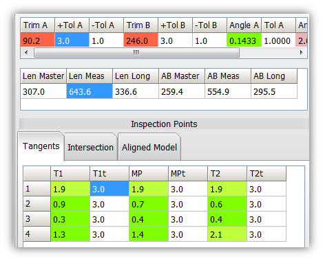
The Tangent chart is represented by a grid of straights for each row with tangent points and midpoints for each straight:
Technically a tangent point is the point where any straight meets any bend. These are considered the best points for qualifying a tube shape because the are the points that most closely approximate the walls of a tube gauge. The two end points are an exception to the technical tangent definition given above. There is no bend attached to these points. But these points (T1d in straight 1, and T2d in the last straight) still have value in determining if the part is the correct shape, so it is convenient to include them in this chart and grid - even though they are not really tangents. The general rule is this: If the tangent points are within tolerance, then it follows that the shape of the part - based on the straights - fits well enough inside the tolerance envelope in order to qualify. In GD&T, this is often referred to as the centerline profile. |
How to Understand the Chart
|
The chart is represented by a grid of straights for each row, and critical inspection points along each straight:
Technically a tangent point is the point where the straight meets the bend. These are considered the best points for qualifying a tube shape because they most closely approximate a profile gauge. The only exception are the points at the end - where no bend is attached. But these points (T1d in straight 1, and T2d in the last straight) still have value in determining if the part is the correct shape. If the tangent points are within tolerance, then it follows that the shape of the part - based on the straights - fits well enough inside the restricted path or envelope in order to qualify. In GD&T, this is often referred to as the centerline profile. |
How to Set the Tolerance
| You can set the tolerance in two places in VTube. One place is in the System Options / Measure 2 menu. |
| The second place to edit the value is in the VTube-LASER Measure Setup menu's "Other" tab menu. |
Choosing Values
|
Set the Default
|
Set the default value by clearing the VTube project, then changing the value, then saving the setup to the default file in the System Options - Project Setup menu. |
Other Pages
- Back to VTube-LASER


