


|
This page describes the use of the VTube-STEP and VTube-LASER to STAR bender new data setup and corrections using the STAR SVNet protocol.
|
|
Back to VTube-LASER
Network Protocol
|
VTube-STEP and VTube-LASER use a modified Supravision Network protocol to send new part data and bender part corrections to STAR EVO benders.
We call the protocol "STAR SVNet". It runs through a standard network connection - wired or wireless.
|
|
STAR SVNet Data Protocol Information
These are important facts to know about this protocol.
- The STAR SVNet protocol is network protocol. It can be setup over a network or for use with a thumb drive.
- The protocol can be used to send NEW part data or CORRECTED data to the bender.
- Unlike the standard SVNet protocol, the STAR SVNet protocol is unidirectional. Data only flows from VTube to the STAR.
- Th reason it is unidirectional is because the STAR control is not designed to respond to VTube-LASER RECALLS during bender correction.
- Therefore, the RECALL button in the VTube-LASER Bender Setup window is always disabled with the STAR SVNet protocol.
- The STAR SVNet protocol requires that the operator ensure that the pre-correction data in the blue columns matches the current STAR bender data before corrections are sent (Orange columns) to the bender. VTube-LASER will warn the operator of this in a simple dialog before the SEND is completed.
|
|
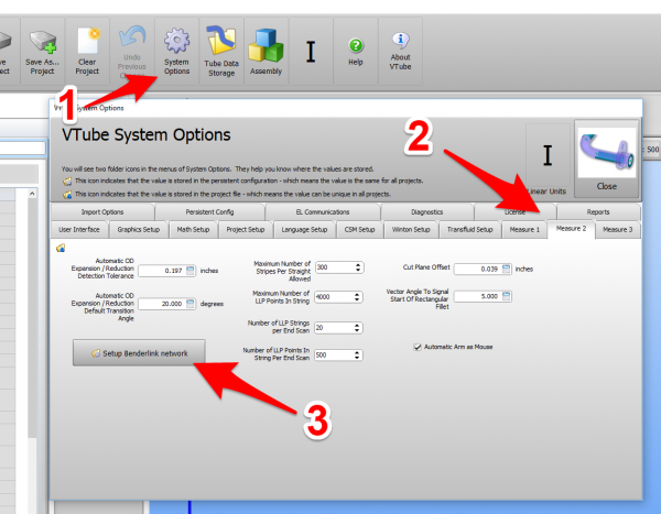
BENDERLINK SETUP STEPS FOR VTUBE-LASER
- Click on Systems Options in the toolbar at the top of the screen.
- Enter the Measure 2 tab menu.
- Enter the Setup Benderlink Network menu.
|
|
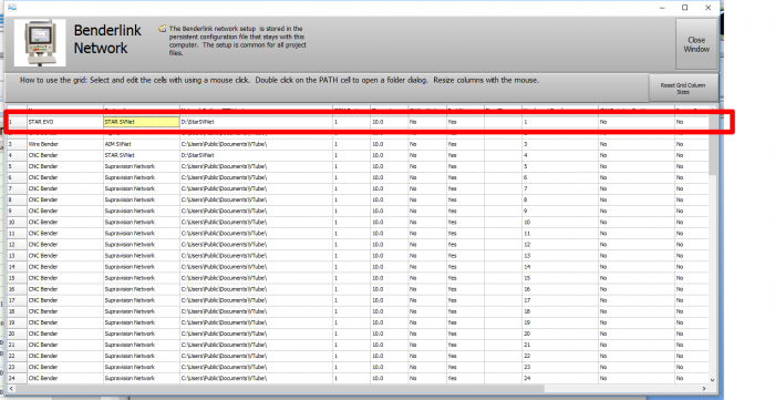
STEP 2: Setup the Benderlink Network Grid for STAR SVNet Protocol
- Choose an unused row in the grid for a new STAR bender setup.
- Assign a bender name that will help operators identify which bender this is. This text will be displayed at the top of the Bender Setup menu.
- Assign the STAR SVNet protocol.
- Enter the path to the shared drive or folder in the NetPath field. This path should point to the network folder that will receive Supravision files from VTube. (The value shown on the screen is only an example.)
- Enter the IP address in the PING IP ADDRESS field if it is a fixed field. (This is not required. It allows VTube to ping the address to see if the network location is active before trying to open communications.)
- If the STAR bender rotates the check/collet Clockwise positive, then select YES in the CW Rotation Positive cell.
- Press Close to save the settings. VTube will save these values to a persistent configuration file that will not change unless you change them in this grid.
|
|
 How to SEND CORRECTION Data to the STAR Control from VTube-LASER
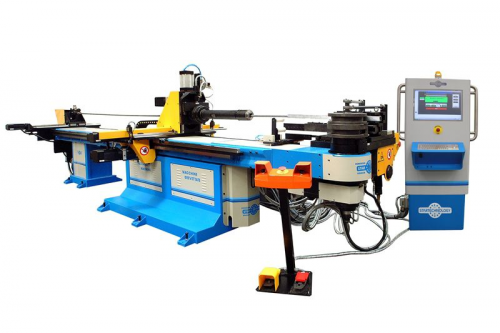
STEP 1 - Bend the Tube
|
Bend the tube in the STAR bender.
|
|
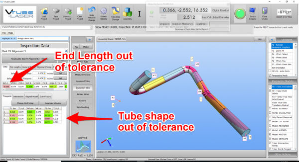
STEP 2 - Measure the tube with VTube-LASER
|
Measure and align the tube to determine if it qualifies by falling within the envelope tolerance for the tube shape.
In the screen shot on the right, the red on the top left shows that the first END "A" LENGTH is out of tolerance.
Also, the red cells in the tangent point grid show that the measured tube centerline shape is out-of-tolerance.
Also - VTube is very visual. The solid model on the right shows exactly where the part is out is exceeding the tolerance.
Click on the image to zoom in to see the values.
|
|
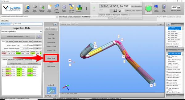
STEP 3 - Enter BENDER SETUP
|
Click on the BENDER SETUP button in the Navigation Pane.
|
|
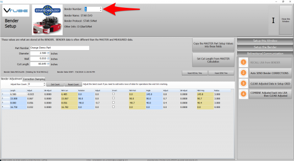
STEP 4 - Choose the BENDER NUMBER
|
Set the correct bender number at the top of the window.
You can select up to 100 different benders.
The Bender Protocol should say "STAR SVNet". (This assumes that you have already configured VTube's Benderlink in the Systems Options as described in the previous section.)
|
|
STEP 5 - COPY the Data from VTube-LASER's Main Memory
|
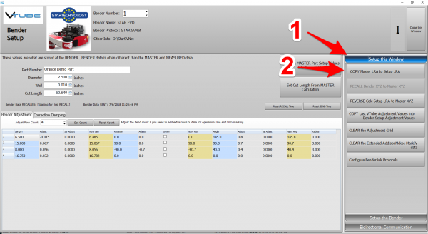
If this is the first correction, then the Bender Setup screen may show no data. If this is the case, then it is necessary to update the Bender Setup screen from VTube-LASER's main memory like this:
- Press "Setup this Window".
- Press "Copy Master LRA to Setup LRA".
|
|
STEP 6 - OPTIONAL STEP - You Can Manually Change the ADJUSTMENT Values
|
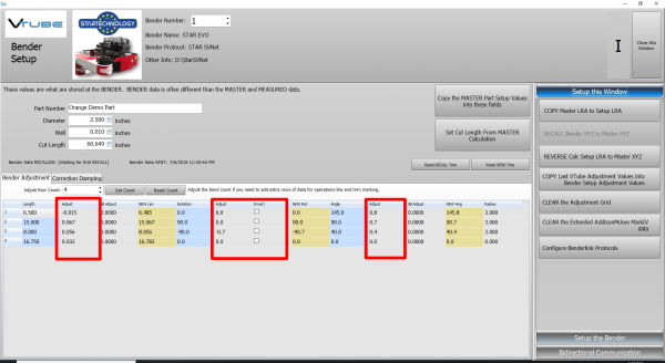
You can manually change the ADJUSTMENT values before sending corrections if you want to. Some users like to set the first and last Length adjustment to zero in order to keep the start position of the carriage in the same place - for when they have extra length on the ends.
If you want to, it is even possible to invert the rotation direction to keep the tube from hitting the bender during rotations.
|
|
STEP 7 - Send Corrections to the HERBER
|
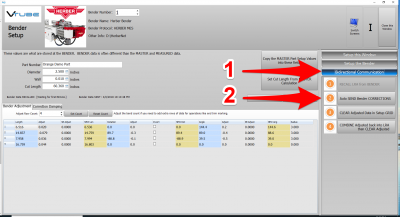
Press "Auto SEND Bender CORRECTIONS". VTube-LASER will let you select a path, then save a MES file to that path.
|
|
STEP 8 - The SEND to BENDER Complete Window
|
A window should appear for a few seconds indicating that the Send to the Bender is complete.
You can allow this window to close on its own in a few seconds, or press the close button to close it immediately.
|

|
STEP 9 - IMPORT the Correction Data at the HERBER Control
|
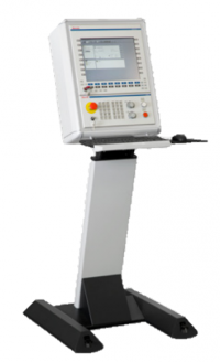
Move to the HERBER control and follow these steps:
- Click on “Read measurement from machine” in the Communications menu.
- Select your measuring system (VTube).
|

|
- Select the .MES file VTube-LASER just created. When you click OK, the HERBER software will ask if you want to delete the MES file after importing.
- To apply all corrections from the mes file, click on “Save all measurements” and continue bending. You are not required to stop the machine to do this. The HERBER cell allows for correction in an automated production cell in realtime. The corrections will be applied for the next part bent.
|

|
- It is also possible to delete or save individual correction values by marking a bend and opening the measure tab.
|

|
STEP 10 - REPEAT STEPS 1 THROUGH 9
|
Bend the corrected tube starting in Step 1, then measure it again (Step 2) and follow the rest of the steps until the part is within tolerance.
|
|
Other Pages


