VTube Reverse Calc from MIL-D-9898C Absolute Bender Data to Centerline XYZ Data
|
This military spec bender chart data chart can converted by VTube-STEP and VTube-LASER in the LRA grid section of the Part Data menu. |
Contents |
General Principals for the Military Specification
ABSOLUTE LENGTHS
|
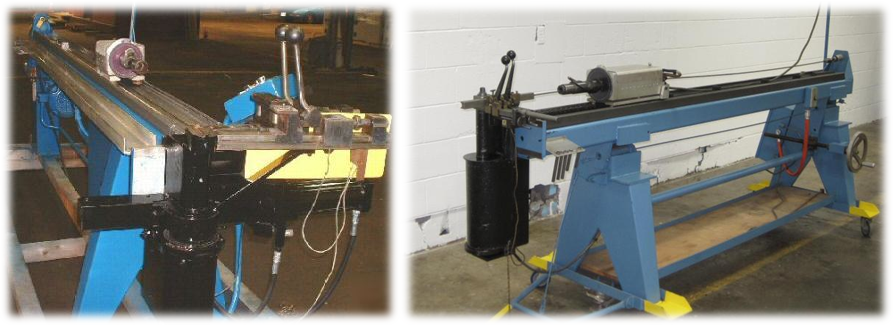
This bender data spec uses ABSOLUTE LENGTHS between bends as if they were derived from a tape-measure attached to the Feed axis of a bender. CONRAC benders sometimes had tape measures riveted along the rail of the carriage that moves along the length of the bender. The lengths indicate where each bend begins. |
ABSOLUTE ROTATIONS
|
According to the spec, the bender data uses ABSOLUTE ROTATION data (twist angle between the planes of the bends). It is absolute because it always depends on the rotations in all preceding bends accumulated. The dial on an absolute rotation spindle reads from 0 to 360. |
DRAW BENDING
|
Although it seems to be ambiguous in the specification, most of the part data from this specification assumes DRAW bending versus COMPRESSION bending - which means the LENGTH values move the carriage so that the tube is positioned at the start of each bend (for clamping and drawing around the bend die that rotates with the bend arm) rather than the end of each bend (for clamping with rollers or wipers and compressing around the bend die that does not rotate with the bend arm). |
|


