
About this Page
|
This page describes the setup and use of the VTube to BLM communications.
|
|
The Basics of How It Works
- VTube-LASER RECALLS, MODIFIES, and SAVES data directly in ".BLM" files. A communications link can be setup through a standard Windows network connection.
- The communication is bi-directional to and from the bender. It is possible to RECALL data from the BLM using the .BLM file format.
- The data that is included in the BLM file that the AMOB can read is the BENDER data (Xc axis, Yc Axis, Zc Axis). The data also includes the diameter and the cut length.
- The protocol does not send the RADIUS data. Sending radius data causes the VGP-3D to reset the tools and rebuild all custom commands - so VTube-LASER avoids sending this data.
|
|
Communications Setup at the BLM Bender
- Connect the BLM bender to the network using a standard Ethernet cable.
- Setup a shared network location either in the BLM windows control or in a network path on your network.
- If you share a folder on the BLM control, then create a user with a username and password that can be used to login to the computer from the VTube-LASER computer.
|
|
Setup Benderlink at VTube-STEP or VTube-LASER
Entering Benderlink Setup
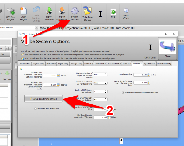
- Enter the VTube System Options menu.
- Enter the Measure 2 tab menu.
- Enter the Setup Benderlink Network menu.
|
|
Setup the Benderlink Network Grid for the BLM Bender
- Choose an unused row in the grid for a new BLM bender setup. (Click on the image at the right to see a zoomed image.)
- Assign a bender name that will help operators identify what this bender is. This text will be displayed at the top of the Bender Setup menu.
- Set the protocol to BLM Data.
- Enter the path to the shared drive or folder in the NetPath field. Use the same location as the BLM setup. VTube accepts UNC names as well as regular paths with drive letters.
- Enter the IP address in the PING IP ADDRESS field if it is a fixed field. (This is not required. It allows VTube to ping the address to see if the network location is active before trying to open communications.)
- Most BLM benders handle Positive rotations as Clockwise, so you will probably need to enter "YES" for this option (so that the rotations are not corrected in the wrong direction).
- Press Close to save the settings. VTube will save these values to a persistent configuration file that will not change unless you change them in this grid.
|

|
How to SEND CORRECTION Data to the BLM Control from VTube-LASER
After Bending the Tube
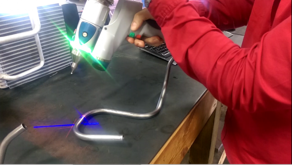
Bend a tube then measure it with VTube-LASER.
Measure the tube with VTube-LASER
Measure and align the tube to determine if it qualifies by falling within the envelope tolerance for the tube shape.
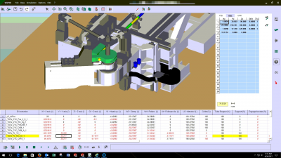
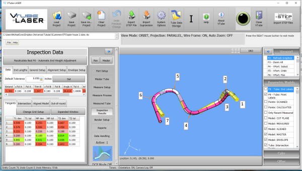
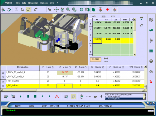
In the VTube-LASER screen shot, you see the actual result of the first tube not qualifying in shape. The red cells in the tangent point grid on the lower left show that the measured tube centerline is out-of-tolerance.
|
|
Correct the BLM with VTube-LASER - Enter BENDER SETUP
|
Follow these steps in the VTube-LASER:
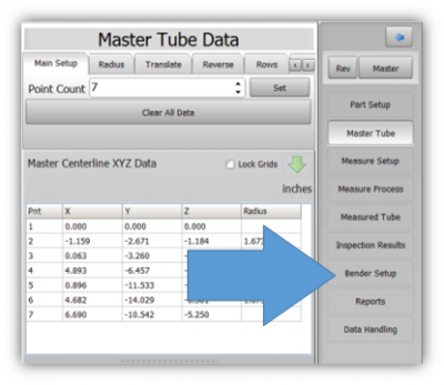
Press the "BENDER SETUP button in the Navigation Pane.
|
|
INITIAL RECALL Setup of Bender Setup Window
|
The first time in this window for a new part will require these steps before you can correct the BLM bender. These steps assume that you have programmed a part in the bender, and that you have measured and aligned a part.
STEP 1 - Set the correct bender number at the top of the window. The BLM bender should display if you have already setup the bender protocol in the Benderlink grid.
STEP 2 - Click on the "Bidirectional Communication" button.
STEP 3 - Click on the "RECALL LRA from BENDER" button.
STEP 4 - Select the BLM file to open.
|


|
RECALL Warning Boxes
|
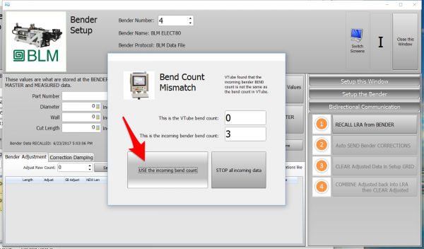
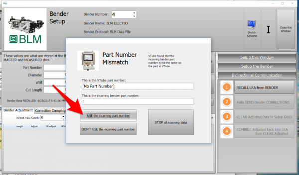
VTube-LASER will probably warn you that the incoming data count and part number does not match what is in VTube-LASER.
Allow the process to increase the bend count, and accept the incoming part number.
|
|
AFTER RECALL
|
After the RECALL, the Blue Columns will show the data that is programmed in the BLM control.
|

|
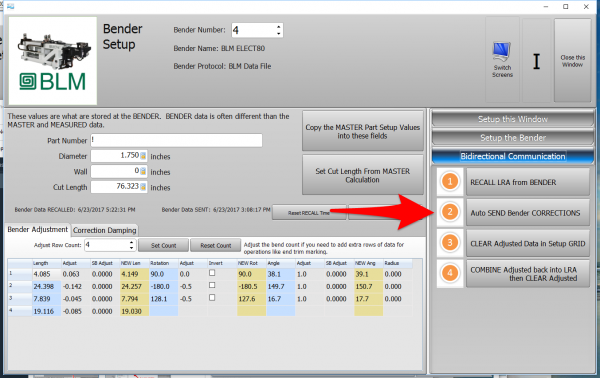
Send the Corrections to the BLM File
|
Save the Correction data to the file for the BLM to import.
STEP 1 - Click on Bidirectional Communication
STEP 2 - Click on AUTO SEND.
STEP 3 - Save the new BLM file to the network location.
|
|
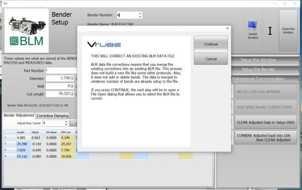
Dialogs Inside the Send Corrections Feature
|
STEP 1 - The first dialog explains how communications happens - but file merge.
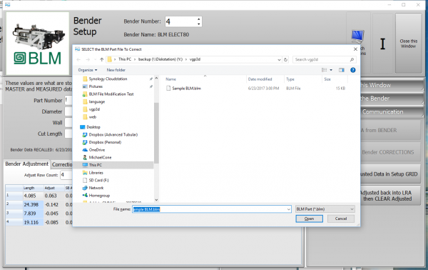
STEP 2 - In the SAVE dialog, select the BLM file to merge data into, then press Save.
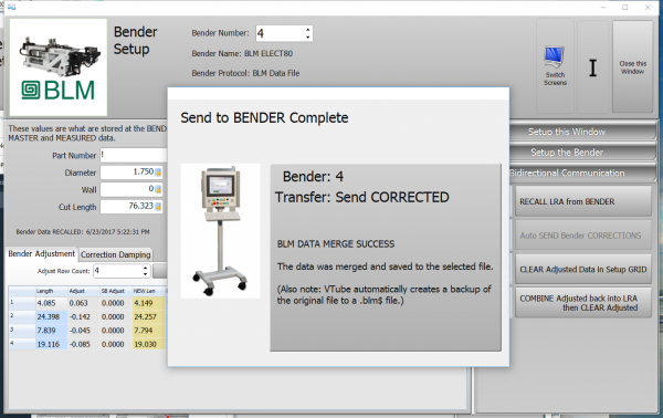
STEP 3 - VTube will show a timed message about the data merge.
|
|
Load the New BLM File Into the VGP-3D Software at the BLM
|
Load the BLM data VTube just saved into the VGP-3D software.
|
|
CRITICAL STEP: Initialize the New Values in the VGP-3D Software at the BLM
|
This next step is CRITICAL for proper operation of the BLM software. Without it, the new data will not be sent to the PLC.
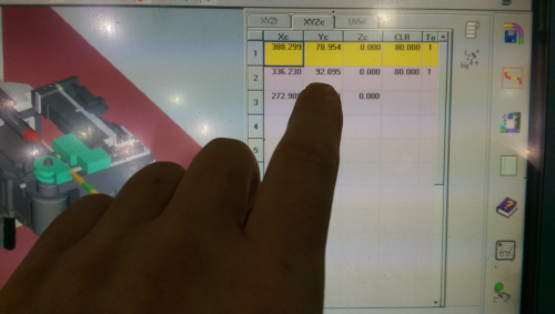
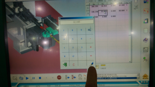
- Touch any value on the XYZc grid.
- Without changing the value, press the Enter button (the pen button).
This will initialize the data in the rest of the BLM program.
|
|
Send the Program to the Bender and Bend the Part
|
- Send the new data to the bender.
- In the BLM, you can run the simulator with the new data.
- Bend the corrected part.
- Take it back to VTube-LASER to measure again.
|

|
Other Pages


