Difference between revisions of "Eaton Leonard Lightspeed Communications Setup"
(→Communications Test on the LightSpeed Side) |
(→VTube-LASER Communications Test on the LightSpeed Side) |
||
| Line 76: | Line 76: | ||
<br><br> | <br><br> | ||
| − | ==VTube-LASER Communications Test | + | ==VTube-LASER Communications Test With the LightSpeed== |
| + | |||
| + | VTube-LASER is the version of VTube that communicates with a FARO arm in order to measure tubes and correct benders. It's communications capabilities are more sophisticated than VTube-STEP. VTube-STEP can send data to the bender. VTube-LASER can SEND and RECALL. This section is for testingthe LightSpeed control with with VTube-LASER. | ||
<table> | <table> | ||
Revision as of 21:31, 18 December 2015
|
This document outlines the basic communications setup for a Lightspeed control. |
|
|
Network Communications Setup Instructions for the Eaton Leonard LIGHTSPEED
|
This is good for use in connecting with our VTube-LASER, VTube-STEP, and Benderlink software packages. All of them are equipped with the Supravision Network protocol - which is a protocol LightSpeed understands. |
STEP 1: System Menu and Administrative Control
|
Change to the Systems menu. If you are not running the operator station as an administrator, then press SECURITY and enter the administrator code. (The default code is "123".) Press the DEVICE CONFIG button. |
STEP 2: Device Config / Machine Menu
|
In DEVICE CONFIG, enter the MACHINE menu. Select a Measure Machine tab. LightSpeed can store four simultaneous measuring center setups for connection to multiple measuring centers.
|
VTube-LASER Communications Test With the LightSpeed
VTube-LASER is the version of VTube that communicates with a FARO arm in order to measure tubes and correct benders. It's communications capabilities are more sophisticated than VTube-STEP. VTube-STEP can send data to the bender. VTube-LASER can SEND and RECALL. This section is for testingthe LightSpeed control with with VTube-LASER.
|
In order to communicate with the LightSpeed control, it's necessary to switch on remote communications in the control in the user interface. |
STEP 1: Exit AUTO Mode
|
Be sure to exit AUTO mode if that is the mode it is currently in. LightSpeed does not communicate if it is in AUTO mode. |
STEP 2: Enter the Vector Menu
|
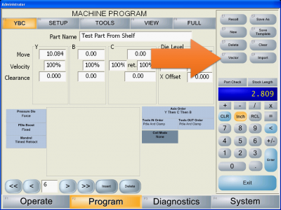
Click on the "Vector" button on the right side of the screen. |
STEP 3: Choose the VMM for VTube
|
Newer versions of LightSpeed let you choose which measuring center to communicate with. |
STEP 4: Allow Network Control
|
In the VECTOR menu, press the "Allow Network Control" button until it turns orange. (Orange indicates that it is toggled on.) |
STEP 5: SEND a Part from the VTube-LASER
|
From the measuring center, send a part to the LightSpeed. (This assumes that the connection has been made and that the SVNET protcol is being used, and that the appropriate bender number is used at the measuring center. The screen on the right shows an example Bender Setup screen in VTube-LASER for communication. |
STEP 6: Observe the LightSpeed Communications Status Box
|
The Communications Status box in the LightSpeed Vector menu should show activity - like that the incoming file was saved. |
STEP 7: Perform a RECALL at VTube-LASER
|
Change any value in the YBC data. Make the value change easily recognizable for when we recall the data in VTube-LASER. |
Solving LightSpeed Bend Die / Incoming RADIUS Mismatch Issue
|
If you send a part to the LightSpeed that has dies that do not match the current die setup, then the Bend Die columns in the VIEW page will turn red - indicating a problem. |
SOLUTION 1: Change the Radius Values in VTube before Sending Data
|
It's easy to change the radius values for a tube model before sending the data to the bender. In the video example, you will see a radius value of 1". However, in the Eaton Leonard LightSpeed, the die centerline radius is 1.125". So, just before sending data to the bender, we change the radius to match the bend die on the bender. This does not change the shape of the tube in space. It only changes the lengths between bends. |
SOLUTION 2: Be sure the TOOLS Page Is Setup With Non Zero Values
|
When you clear a part, the process also can clear the tool page so that all the values are reset to zero. The image on the right shows what happens after clear of a program in the LightSpeed |
SOLUTION 3: Be sure the YBC Page CENTERLINE RADIUS Values Match the TOOL Page Values
Other Pages
|


