Difference between revisions of "Cable Spec 35"
From ATTWiki
| Line 11: | Line 11: | ||
| − | [[image:db9_rej45_cb-el1_pinout.jpg|800px]] < | + | [[image:db9_rej45_cb-el1_pinout.jpg|800px]] <be> |
| + | |||
| Line 24: | Line 25: | ||
</tr> | </tr> | ||
</table> | </table> | ||
| + | |||
| + | ==Breakout Tester== | ||
| + | |||
| + | Use a breakout tester for continuity checks like this: | ||
| + | <br><br> | ||
| + | [[image:cable_CB-EL1_breakout_test.png|800px]] | ||
| + | |||
| + | |||
| + | ==In the Box== | ||
<table> | <table> | ||
Revision as of 16:45, 23 August 2022
|
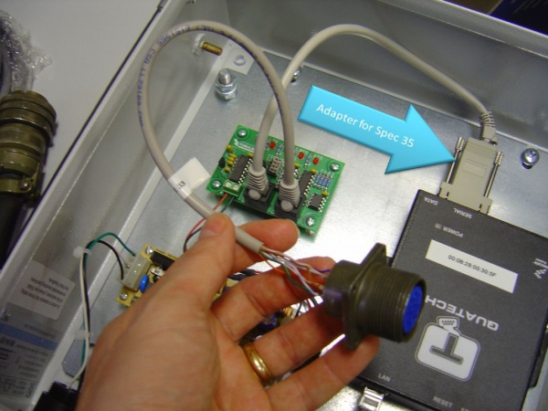
This is the wiring schematic for the RJ45 to DB9 female adapter for the CB-EL1 RS232D port on the board. |
|
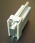
This is an image of an RJ45 to DB9 adapter with the above wiring. The DB9 port is female to attach to a standard PC male port. |
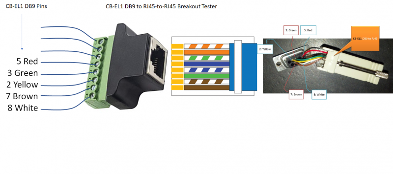
Breakout Tester
Use a breakout tester for continuity checks like this:

In the Box
Other Pages
- Back to Cable Specs


