Wiring: Keeping the Mitsubishi Drives Powered when E-Stop
Contents |
About
On some older benders, the Mitsubishi drives power down when E-Stop is pressed. This approach causes the Feed and Rotate axes to loose the HOME status in the I2T modules when the E-Stop is pressed.
So with newer CNC Bender software, it is necessary to keep the Mitsubishi drivers powered - even when the E-Stop is activated.
STEP 1: Check the State of the Drives at E-Stop
|
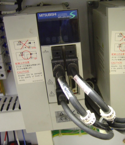
Set MASTER POWER ON, Press the E-Stop, then examine the drives LED screens. If they are blank, then the drives are off, and you will need to perform this wiring change during a CNC Bender upgrade.
|
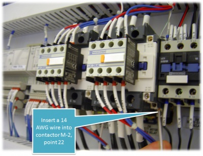
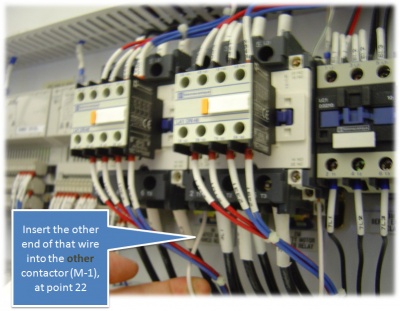
STEP 1: Wire Jump
Wire jump point 22 in M-1 to point 22 in M-2
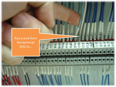
STEP 2: Attach a Power Line
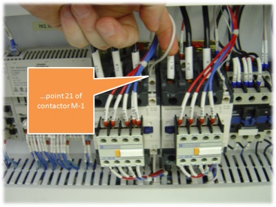
Tap into power by finding wires 2432 at the terminal strip. Run a wire from the strip up to an into point 21 of the M-1 contactor
STEP 3: Run the Mitsubishi RESET Wire To M-2
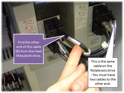
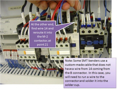
- Run wire from point 14 in the CN1B cable on the Mitsubishi drives to point 21 of the M-2 connector.
- There is a cable running from both the Feed and Rotate drives. Point 14 from both cables must be found and used to connect to the M-2 contactor.
- If the cable is a stock Mitsubishi cable, then there will be many wires in the cable. Wire 14 will be white with a green stripe
- If there is no wire 14, then you will need to run a small wire (24 AWG) into the connector at the drives. The connectors use solder cups. Solder the wire into point 14 at the CN1B connector.
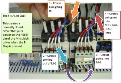
Finished! - Circuit Created
This is an image that shows the circuit created. Click on the image to see a closeup.
Other Pages
- Back to the CNC Bender Page
- Back to the CNC Bender Technical Notes Page
