|
|
| Line 62: |
Line 62: |
| | | | |
| | In VTube-LASER click on the Cut Plane icon at the bottom of the Navigation Pane, then click on Measure Cut Plane in the "New" tab menu. The Laser scanner will turn off automatically.<br><br> | | In VTube-LASER click on the Cut Plane icon at the bottom of the Navigation Pane, then click on Measure Cut Plane in the "New" tab menu. The Laser scanner will turn off automatically.<br><br> |
| | + | </td> |
| | <td> | | <td> |
| | [[image:vtube-laser_v2.7_measure_new_cutplane.png|300px]]<br> | | [[image:vtube-laser_v2.7_measure_new_cutplane.png|300px]]<br> |
Revision as of 16:02, 18 October 2016
What Are Cut Planes?
Cut planes allow VTube-LASER to define a plane of a table or other surface in order to cut LASER* points from being used in measurements to VTube-LASER. (*As of VTube-LASER Version 2.7, ALL TACTILE measurements ignore cut planes.)
|
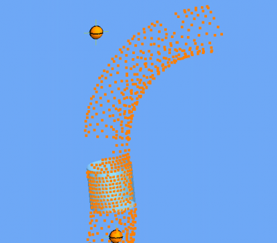
Without the Cut Plane Offset set properly, scanning data from a cylinder on a table would appear like this to VTube-LASER.
|

|
|
We can use orbit to tilt the view slightly. You can see how the table points are included in this scan of an outer diameter.
|

|
|
Increase the Cut Plane offset and you will remove all outliers from the table surface.
|

|
How to Create a Cut Plane
Cut planes are created with four measurements using the ball probe.

STEP 1
In VTube-LASER click on the Cut Plane icon at the bottom of the Navigation Pane, then click on Measure Cut Plane in the "New" tab menu. The Laser scanner will turn off automatically.
|

|
STEP 2
Follow the instructions in the yellow guide box.
Touch the table with the ball probe and press and release the green button. |
</td>
<td>
 </td>
</td>
<tr>
<td width=300>
STEP 3
Move the probe to another place on table. The further away from the first point, the better for the math engine.
Press and release the green button.</td>
<td>
 </td>
</tr>
<tr>
<td width=300>
STEP 4
Move the probe to another place on table in a way that forms an approximate equilateral triangle. (It is best to not make the triangle a thin sliver triangle.
Press and release the green button.</td>
<td>
 </td>
</tr>
<tr>
<td width=300>
STEP 5
Move the probe upward above the table. This forms the up direction of the plane (also called the "normal" to the plane)
Press and release the green button.</td>
<td>
 </td>
</tr>
<tr>
<td width=300>
STEP 6
The Cut Plane Offset menu will display.
Enter the cut plane offset in this window. There must be an offset or table points will eventually be included in the scan.
Granite Surface Plates
0.039" offset is acceptable
Office Tables
0.125" offset is usually acceptable (Tables are much less flat than surface plates - so the offset needs to be greater than on surface plates.)
Offset Distance Rule
- VTube can work with offsets that are up to about half the diameter of a tube.
- This would mean that small diameter tubes that are less than 0.25" diameter might not scan well on a regular office table.
</td>
<td>
 </td>
</tr>
</table>
Principles for Using Cut Planes
1 - Use any number of MULTIPLE CUT PLANES simultaneously.
The new Cut Plane Setup Control window can be opened at any time to control any number of multiple cut planes simultaneously.

2 - CUT PLANES can now be measured ON-THE-FLY during any tube measurement.
In previous versions, the CUT PLANE measurement had to be performed before you started measuring the tube. Now you can measure new cut planes even if you are in the middle of measuring a tube - then continue where you left off after you measure a new Cut Plane.

3 - CUT PLANES can be made ACTIVE or INACTIVE at any time
The ACTIVE check boxes in the Cut Plane List let you switch them on or off at any time.

4 - The DRO (Digital Readout) shows if the scan is below the Cut Plane before you scan
Have you ever wondered why the arm wasn't measuring, only to find out that you were below the cut plane? This will give you a clear indication if you are below the cut plane - BEFORE you press the green button

5 - CUT PLANE setups are now stored in project files
Because of this new feature, a new dialog appears when you are changing projects. This gives you the flexibility of choosing to keep the current setup, or to load the setup inside the project file.

6 - The CUT PLANE setup can be exported and imported using XML files
- VTube can now export and import entire CUT PLANE setups using the XML file format.
- VTube uses XML files to store the Cut Plane setup automatically between shut down and switch on. So you no longer have to worry about losing the current Cut Plane setup when you close VTube. VTube will automatically store it for you for use in future measuring sessions. This is ideal for a majority of our customers that never change the arm or the measuring table in relationship to each other.

7 - NEW INNOVATION for Measuring Parts In Densely Packed Areas: DIAMETER CUT PLANES
Measure Across Several Diameters - VTube will find the correct straight

This new feature lets you scan across several diameters or objects of any kind - and still AUTOMATICALLY find only the diameter you want to keep.


AIM Inc. - Wirebending Applications
The feature was developed to solve a need that we encountered at AIM Inc. when measuring wire bent parts. The orange part shown below is a sample test piece that is formed from 0.2 inch diameter wire. When measuring this part the FARO scanner stripe often crosses four straights at the same time.

Illustration of the Issue
Imagine the HD (blue) laser stripe measuring one of these four straights. In order to measure one, it is very hard to orient the beam in a way that avoids the three straights you don't intend to measure. This is the easy way to measure one of these four straights:

However, touching four straights at the same time will not allow VTube to calculate a centerline of any one of these straights - unless you use the DCP feature. The DCP feature follows some simple rules to allow VTube to sort out and select the one straight that you intend to measure - every time.
It works great on tube assemblies too - like headers for multiple tubes close to each other, and HVAC assemblies where tubes pass close to objects like evaporators.
Tutorials On How DCP Works
 ENHANCED - Smarter Scanned Point Cloud Display for FAST Redraw Speed
Why This Feature Was Needed
The issue is that VTube can handle extremely dense point clouds internally (in memory) - but graphics cards cannot keep up with the increased load from the new Bend Profile feature. So we changed VTube to automatically limit the number of points displayed on the screen.
VTube was redesigned so that point clouds would be displayed densely enough (regardless of tube diameter), and fast enought (regardless of how many points are actually in memory).
Goals for Calculation of Point Cloud Density for Display in VTube
Goal 1: VTube needs to display points quickly on the screen.
Goal 2: VTube needs to show an appropriate number of points based on the diameter being scanned.
|

|
How it Works
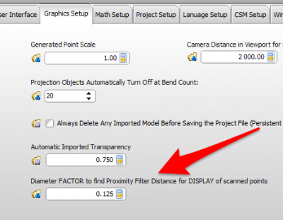
In order to better anticipate how to draw dense point clouds, VTube has this new field in the System Options / Graphics Setup Tab.
This new Diameter Factor value is multiplied against the current diameter to determine how close the displayed points should be on the screen. The default diameter factor value is 0.125. So, for example on a 2 inch OD tube, the points are displayed no closer than 0.25" on the screen. However, for a 0.25" OD tube, the point separation changes so that they display no closer than 0.031" (.25 x .125).
It is Not Used in End Scans
This feature has no impact on END SCANS. End scan point clouds are always display no closer than 0.005" (.12 mm) - regardless of the diameter.
|

|
Diagnosing Problems
It has been our experience that there are two conditions where the Cut Plane is likely to fail to work properly:
- If the wrong ball probe is selected in the FARO probe compensation menu, then the cut plane may fail.
- If the ball probe was never calibrated using the FARO Compensation window, or is not calibrated properly, then the cut plane has a VERY HIGH chance of failing. We have seen Cut Plane issues that are tied back to this problem.
Other Pages


