Difference between revisions of "Cable Spec 26"
From ATTWiki
(→Cable Pinout) |
|||
| Line 37: | Line 37: | ||
<tr> | <tr> | ||
<td bgcolor=#F0F0F0 width=200 align=right> | <td bgcolor=#F0F0F0 width=200 align=right> | ||
| − | + | End A | |
</td> | </td> | ||
| Line 45: | Line 45: | ||
<td bgcolor=#F0F0F0 width=200 align=left> | <td bgcolor=#F0F0F0 width=200 align=left> | ||
| − | + | End B | |
</td> | </td> | ||
</tr> | </tr> | ||
| Line 57: | Line 57: | ||
<tr> | <tr> | ||
<td width=175 align=right> | <td width=175 align=right> | ||
| − | + | Red | |
</td> | </td> | ||
<td width=25 align=right bgcolor=#90EE90> | <td width=25 align=right bgcolor=#90EE90> | ||
| − | + | A | |
| + | </td> | ||
| + | </tr> | ||
| + | |||
| + | <tr> | ||
| + | <td width=175 align=right> | ||
| + | Red/Black | ||
| + | </td> | ||
| + | <td width=25 align=right bgcolor=#90EE90> | ||
| + | B | ||
| + | </td> | ||
| + | </tr> | ||
| + | |||
| + | <tr> | ||
| + | <td width=175 align=right> | ||
| + | White | ||
| + | </td> | ||
| + | <td width=25 align=right bgcolor=#90EE90> | ||
| + | C | ||
| + | </td> | ||
| + | </tr> | ||
| + | |||
| + | <tr> | ||
| + | <td width=175 align=right> | ||
| + | White/Black | ||
| + | </td> | ||
| + | <td width=25 align=right bgcolor=#90EE90> | ||
| + | D | ||
</td> | </td> | ||
</tr> | </tr> | ||
| Line 69: | Line 96: | ||
</td> | </td> | ||
<td width=25 align=right bgcolor=#90EE90> | <td width=25 align=right bgcolor=#90EE90> | ||
| − | + | E | |
</td> | </td> | ||
</tr> | </tr> | ||
| Line 75: | Line 102: | ||
<tr> | <tr> | ||
<td width=175 align=right> | <td width=175 align=right> | ||
| − | + | Green/Black | |
</td> | </td> | ||
<td width=25 align=right bgcolor=#90EE90> | <td width=25 align=right bgcolor=#90EE90> | ||
| − | + | F | |
</td> | </td> | ||
</tr> | </tr> | ||
| Line 84: | Line 111: | ||
<tr> | <tr> | ||
<td width=175 align=right> | <td width=175 align=right> | ||
| − | + | Blue | |
</td> | </td> | ||
<td width=25 align=right bgcolor=#90EE90> | <td width=25 align=right bgcolor=#90EE90> | ||
| − | + | G | |
</td> | </td> | ||
</tr> | </tr> | ||
| Line 93: | Line 120: | ||
<tr> | <tr> | ||
<td width=175 align=right> | <td width=175 align=right> | ||
| − | + | Blue/Black | |
| + | </td> | ||
| + | <td width=25 align=right bgcolor=#90EE90> | ||
| + | H | ||
| + | </td> | ||
| + | </tr> | ||
| + | |||
| + | <tr> | ||
| + | <td width=175 align=right> | ||
| + | Shield | ||
</td> | </td> | ||
<td width=25 align=right bgcolor=#90EE90> | <td width=25 align=right bgcolor=#90EE90> | ||
| − | + | J | |
</td> | </td> | ||
</tr> | </tr> | ||
Revision as of 17:43, 23 May 2012
|
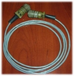
This is the wiring schematic for the Eaton Leonard style current loop cable.
Parts ListConnector
Cable Clamp and Bushing
Reducing Bushing
Cable
|
Cable Pinout
|
End A |
|
End B |
||||||||||||||||||||||||||||
|
|
|
|
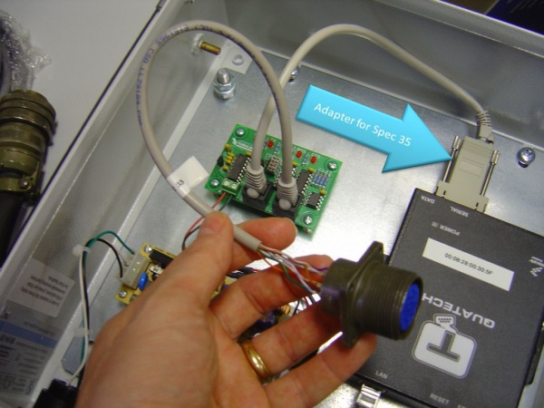
This is an image of an RJ45 to DB9 adapter with the above wiring. The DB9 port is female to attach to a standard PC male port. |

