Difference between revisions of "Wiring: Keeping the Mitsubishi Drives Powered when E-Stop"
(→STEP 2: Find Three Wires) |
(→About) |
||
| (12 intermediate revisions by one user not shown) | |||
| Line 1: | Line 1: | ||
==About== | ==About== | ||
| − | On some older benders, the Mitsubishi drives power down when E-Stop is pressed. This approach causes the Feed and Rotate axes to | + | On some older benders, the Mitsubishi drives power down when E-Stop is pressed. This approach causes the Feed and Rotate axes to lose the HOME status in the I2T modules when the E-Stop is pressed.<br> |
| − | + | ||
| − | + | ||
<br> | <br> | ||
| + | Since CNC Bender software monitors the home state as a way to predict servo module health, it is necessary to keep the Mitsubishi drivers powered - even when the E-Stop is activated. | ||
| + | <br><br> | ||
<table cellpadding="15"> | <table cellpadding="15"> | ||
| − | <tr><td | + | <tr> |
| + | <td>[[image:warning.jpg|100px]]</td> | ||
<td width=300 bgcolor="#f0f0f0"> | <td width=300 bgcolor="#f0f0f0"> | ||
<font size=5>[[image:Gear_warning.jpg]] <b>WARNING!</b><br><br></font> | <font size=5>[[image:Gear_warning.jpg]] <b>WARNING!</b><br><br></font> | ||
| Line 42: | Line 43: | ||
<br> | <br> | ||
| − | ==STEP | + | ==STEP 3: Reroute the Wires== |
| − | + | *Reroute these three ends to the top of the M-1 contactor. | |
| + | *Be sure to place the wires into the proper terminal point (1, 2, or 3). | ||
| + | *If there are other wires in the bottom of the M-2 contactor, then leave them in place. | ||
| + | *Leave the wires that are in the top of M-1 in place. (Double up the 1L1, 1L2, 1L3 and the three "3" wires.) | ||
| + | <br> | ||
| + | [[image:MitsubishiDriveOffAtEStop04.jpg|400px]]<br> | ||
| − | |||
| − | |||
| − | ==STEP | + | ==STEP 4: TEST== |
| − | * | + | *Apply power to the bender (at the main breaker switch outside the bender) |
| − | * | + | *Press the E-Stop |
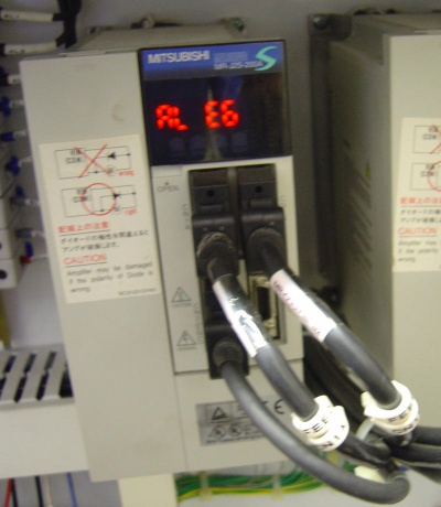
| − | * | + | *The drive should stay powered like shown here. (The AL E6 message will flash): |
| − | + | ||
<br> | <br> | ||
| − | [[image: | + | [[image:MitsubishiDriveOffAtEStop05.jpg|400px]]<br> |
| − | [[image: | + | <br> |
| + | |||
| + | ==Tools/Parts Needed== | ||
| + | <table > | ||
| + | |||
| + | <tr> | ||
| + | <td width=100> | ||
| + | 14 Gauge THHN stranded wire | ||
| + | </td> | ||
| + | <td> | ||
| + | [[image:14awg_thhn_wire.jpg|200px]] | ||
| + | </td> | ||
| + | </tr> | ||
| + | |||
| + | <tr> | ||
| + | <td width=100> | ||
| + | Vinyl Insulate Terminal Pin for 14 gauge wire (See 159-1617 Kobiconn Terminals Pin Blue 16-14 at Mouser.com) | ||
| + | </td> | ||
| + | <td> | ||
| + | [[image:pinterminal.jpg|200px]] | ||
| + | </td> | ||
| + | </tr> | ||
| + | |||
| + | <tr> | ||
| + | <td width=100> | ||
| + | Jumper bar (Automationdirect.com DINnectors DN-82J10) | ||
| + | </td> | ||
| + | <td> | ||
| + | [[image:jumperbar_dn-82J10.jpg|200px]] | ||
| + | </td> | ||
| + | </tr> | ||
| + | |||
| + | <tr> | ||
| + | <td width=100> | ||
| + | Crimper for terminal pins, screw drivers, diagonal cutters for cutting the jumper bar | ||
| + | </td> | ||
| + | <td> | ||
| + | [[image:screwdrivers.jpg|200px]] | ||
| + | </td> | ||
| + | </tr> | ||
| + | |||
| + | </table> | ||
| + | |||
| + | <br><br> | ||
| − | |||
| − | |||
| − | |||
==Other Pages== | ==Other Pages== | ||
Latest revision as of 16:58, 10 February 2011
Contents |
About
On some older benders, the Mitsubishi drives power down when E-Stop is pressed. This approach causes the Feed and Rotate axes to lose the HOME status in the I2T modules when the E-Stop is pressed.
Since CNC Bender software monitors the home state as a way to predict servo module health, it is necessary to keep the Mitsubishi drivers powered - even when the E-Stop is activated.
 |
|
STEP 1: Check the State of the Drives at E-Stop
|
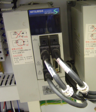
Set MASTER POWER ON, Press the E-Stop, then examine the drives LED screens. If they are blank, then the drives are off, and you will need to perform this wiring change during a CNC Bender upgrade.
|
STEP 2: Find Three Wires
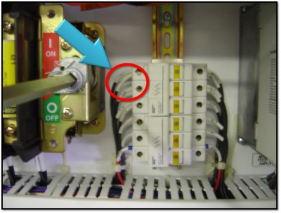
Find the three wires entering the top left side of the white fuse buse to the left of the Feed drives.
- The wires will be labelled 3L1, 3L2, and 3L3.
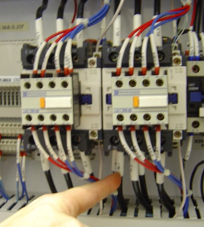
- Trace those wires to the M-2 contactor. (Find the other end.)
STEP 3: Reroute the Wires
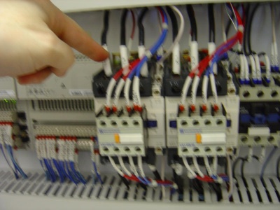
- Reroute these three ends to the top of the M-1 contactor.
- Be sure to place the wires into the proper terminal point (1, 2, or 3).
- If there are other wires in the bottom of the M-2 contactor, then leave them in place.
- Leave the wires that are in the top of M-1 in place. (Double up the 1L1, 1L2, 1L3 and the three "3" wires.)
STEP 4: TEST
- Apply power to the bender (at the main breaker switch outside the bender)
- Press the E-Stop
- The drive should stay powered like shown here. (The AL E6 message will flash):
Tools/Parts Needed
|
14 Gauge THHN stranded wire |
|
|
Vinyl Insulate Terminal Pin for 14 gauge wire (See 159-1617 Kobiconn Terminals Pin Blue 16-14 at Mouser.com) |
|
|
Jumper bar (Automationdirect.com DINnectors DN-82J10) |
|
|
Crimper for terminal pins, screw drivers, diagonal cutters for cutting the jumper bar |
Other Pages
- Back to the CNC Bender Page
- Back to the CNC Bender Technical Notes Page
